Pages

Wednesday, February 24, 2016

Fortigate Firewall Console TFTP Image Recovery

Recently I had a experience to install firmware from a local TFTP server under console control to reset a FortiGate unit to factory default settings.

It was caused by a failed firmware upgrade. System died after reboot. Power light was green, but not other interfaces.

I recorded the all steps in this post.

1. Physical Connections
I were using Fortigate 30D to do this firmware TFTP installation. There are four different types of interfaces on the back of Fortigate 30D.
Here is the photo how Fortigate connected to my laptop with console connection and WAN interface Ethernet connection.
Fortigate 30D Connecting Console and WAN to Laptop

2. Software
2.1 TFTP Software
For TFTP software, I am using TFTPD32. 3CDaemon is also a good option.

TFTPD32 - Open Source tftp server for windows  
3CDaemon V2 - 3com's TFTP server for windows  

2.2 Terminal Client Software
Putty Terminal client communication parameters

  • 8 bits 
  • no parity 
  • 1 stop bit 
  • 9600 baud (the FortiGate-300 uses 115,000 baud) 
  • Flow Control = None  


3. Procedures

3.1 Power Cycle Fortigate 30D

The system told me boot failed. Please check boot device or OS image.

Before that, there were about 6 seconds to wait to interrupt booting process.

3.2 Enter into Configuration mode
Press any key to interrupt booting process after you power cycle the device, following menu will show on the screen.

[C]: Configure TFTP parameters.
[R]: Review TFTP parameters.
[T]: Initiate TFTP firmware transfer.
[F]: Format boot device.
[I]: System information.
[B]: Boot with backup firmware and set as default.
[Q]: Quit menu and continue to boot.
[H]: Display this list of options.

3.3 Press C to Configure TFTP parameters


After you have configured all TFTP parameters, such as Fortigate local ip, network mask, gateway, image name, remote server ip etc, you can review those parameters. But for Fortigate local IP and network mask, it will show N/A. Actually you do not need to worry about it, just select T to initiate TFTP firmware transfer. Fortigate 30D will notify you to connect your TFTP server to WAN port, which is completely different from other Fortigate models, such as 60D. Please check following list to see which port your Fortigate should use to do firmware transfer.

 FortiGate Model                                Interface
=============================================================
50, 50A, 100, 200, 300, 500, 800, 800F          Internal
50B, all 60 models, 100A, 200A                  Internal port 1
100A, 200A (If Internal Port1 does not work)    Internal port 4
300A, 310A, 400, 400A, 500A, 1000 and higher    LAN port 1
1240B                                           port40
Fortigate with a dedicated management port      mgmt1


3.4 Initiate TFTP firmware transfer
After you initiate TFTP firmware transfer, the Fortigate WAN will be turned on.

You will see Firmware is transferring from TFTP server to Fortigate 30D. Once transferring done, you will be notified how you want to save this image for.


Reference:

Technical Note : Loading FortiGate firmware image using TFTP

Monday, February 22, 2016

Cisco ASA Remote Access VPN Configuration 2 - AnyConnect VPN

Basic Cisco AnyConnect full-tunnel SSL VPN uses user authentication by username and password, provides IP address assignment to the client, and uses a basic access control policy. The client also authenticates the ASA with identity certificate-based authentication. Deployment tasks in this post are as follows:
  • Configure the basic ASA SSL VPN gateway features.
  • Configure local user authentication.
  • Configure IPv4/IPv6 address assignment.
  • Configure basic access control.
  • Install the Cisco AnyConnect Secure Mobility Client.
Initially, AnyConnect was an SSL-only VPN client. Starting with Version 3.0, AnyConnect became a modular client with additional features (including IPsec IKEv2 VPN terminations on Cisco ASA), but it requires a minimum of ASA 8.4(1) and ASDM 6.4(1).

Related posts in this blog:
1. Topology

In this post, Cisco Adaptive Security Appliance Software Version 9.1(2) and Device Manager Version 7.1(3) have been used as an example.


DMZ (Security Level 50) interface will be used to simulate external connection to Internet.
INTERNAL (Security Level 100) interface is connecting to local network.


User will come from 172.17.3.62 to access 10.94.200.62 though Anyconnect VPN connection.


2. Basic Configuration

2.1 Interface Configuration

interface GigabitEthernet0/0
 nameif INTERNAL
 security-level 100
 ip address 10.94.200.12 255.255.255.0 
!             
interface GigabitEthernet0/1
 nameif DMZ
 security-level 50
 ip address 172.17.3.12 255.255.255.0 

interface Management0/0
 management-only
 nameif MGMT
 security-level 0
 ip address 192.168.2.12 255.255.255.0 
 no shutdown

2.2 SSH and ASDM Configuration

aaa authentication ssh console LOCAL 
http server enable
http 192.168.2.0 255.255.255.0 MGMT
ssh 192.168.2.0 255.255.255.0 MGMT
username admin password admin

2.3 NAT and Access-list Configuration

INTERNAL network can access all DMZ networks with NAT-ed DMZ interface ip 172.17.3.12. But there is no access from DMZ to INTERNAL.

NAT

Firewall Rule
ICMP Echo reply packets have to be allowed on DMZ interface to make ping working from INTERNAL to DMZ work.

object service icmp-reply

 service icmp echo-reply 0

access-list global_access extended permit object icmp-reply any any 
access-list INTERNAL_access_in extended permit ip any any 

access-group INTERNAL_access_in in interface INTERNAL

access-group global_access global

The following NAT rule is to make INTERNAL network to access DMZ network using DMZ interface ip address.
nat (INTERNAL,DMZ) source dynamic any interface


3. Steps to Enable AnyConnect VPN

3.1 Start VPN Wizards -> AnyConnect VPN Wizard...

3.2 Enter Connection Profile Name
3.3 Create and Use a New Self-Signed Certificate

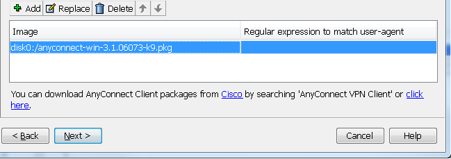
3.4 Add a new Client Image.
It is not .msi file. It has to be a package file.


3.5 Use Local Accounts in ASA as Authentication Method
3.6 Create and Use SSL Connection IPv4 Address Pool

3.7 NAT Exempt
Usually in ASA configuration, there are NAT configured. You will have to exempt your SSL VPN Traffic from NAT configuration
Note: In this wizard, you will only can exempt one local network from NAT configuration. If you have multiple Internal local networks, you will have to work on configuration manually from CLI to exempt all of them from NAT. Else, you will get a deny for your non-NAT-exempt traffic.

3.8 Allow Web Launch


3.9 Configuration Summary
After this screen, your configuration will be pushed from ASDM to ASA device. You will get a notification if there is any configuration wrong.

4. Split Tunneling
Split tunnelling is a feature that you can use in order to define the traffic for the subnets or hosts that must be encrypted. This involves the configuration of an Access Control List (ACL) that will be associated with this feature. The traffic for the subnets or hosts that is defined on this ACL will be encrypted over the tunnel from the client-end, and the routes for these subnets are installed on the PC routing table.

If Split Tunneling enabled on AnyConnect VPN Configuration, VPN user 's traffic to Internal Network (10.94.200.0/24) will be split from other traffic such as Internet Traffic. In this way, AnyConnect VPN user can keep their Internet connection at the same time having local Internal network access.


5. User Policy Control

By default, the user will use DfltGrpPolicy. You can customize your local user to use different VPN Group Policy and different VPN Connection Profile.

In this way, you can control which network user can access, since you can control Split-Tunneling networks in the VPN Connection Profile.


Reference:
Configure AnyConnect Secure Mobility Client with Split Tunneling on an ASA

Friday, February 19, 2016

Cisco ASA Remote Access VPN Configuration 1 - Clientless SSL VPN

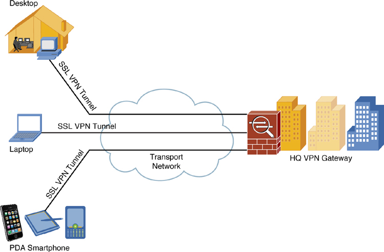
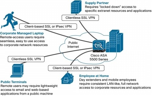
Remote access VPNs let single users connect to a central site through a secure connection over a TCP/IP network such as the Internet. Unlike other common VPN client solutions, the Clientless SSL VPN does not require that a client download and install a VPN client, all communications to the central location (where the ASA is located) are done via Secure Socket Layer (SSL) or its successor, Transport Layer Security (TLS).


This post describes how to build a remote access VPN connection using Clientless SSL VPN feature.
Related posts in this blog:

1. Topology


2. Configuration Steps

2.1 Start VPN Wizards -> Clientless SSL VPN Wizard...


2.2 Set Up SSL VPN Interface
2.3 User Authentication
2.4 Group Policy
2.5 Bookmark List

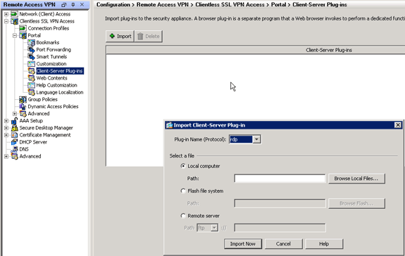
2.6 Import RDP/SSH/VNC Plug-in

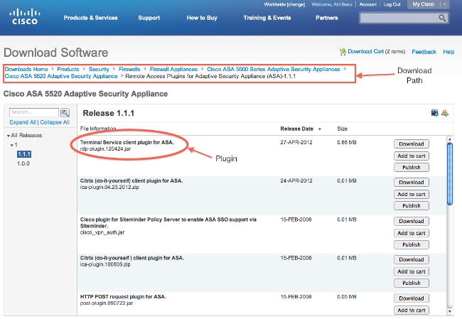
2.6.1 Download RDP/SSH/VNC Java Plug-in

2.6.2 Import Plug-in

2.7 Test


3. Configuration

ciscoasa# show run
: Saved


: Serial Number: 9ALU3EW6LDF
: Hardware:   ASAv, 1024 MB RAM, CPU Xeon 5500 series 2294 MHz
:
ASA Version 9.5(1)200 
!
hostname ciscoasa
enable password 8Ry2YjIyt7RRXU24 encrypted
xlate per-session deny tcp any4 any4
xlate per-session deny tcp any4 any6
xlate per-session deny tcp any6 any4
xlate per-session deny tcp any6 any6
xlate per-session deny udp any4 any4 eq domain
xlate per-session deny udp any4 any6 eq domain
xlate per-session deny udp any6 any4 eq domain
xlate per-session deny udp any6 any6 eq domain
names
!
interface GigabitEthernet0/0
 nameif INTERNAL
 security-level 100
 ip address 10.94.200.12 255.255.255.0 
!             
interface GigabitEthernet0/1
 nameif DMZ
 security-level 100
 ip address 172.17.3.12 255.255.255.0 
!
interface GigabitEthernet0/2
 shutdown
 no nameif
 no security-level
 no ip address
...
!
interface Management0/0
 management-only
 nameif MGMT
 security-level 0
 ip address 192.168.2.12 255.255.255.0 
!
ftp mode passive
dns domain-lookup INTERNAL
dns domain-lookup DMZ
dns domain-lookup MGMT
same-security-traffic permit inter-interface
same-security-traffic permit intra-interface
pager lines 23
logging enable
logging asdm informational
mtu INTERNAL 1500
mtu DMZ 1500
mtu MGMT 1500
no failover
no monitor-interface service-module 
icmp unreachable rate-limit 1 burst-size 1
no asdm history enable
arp timeout 14400
no arp permit-nonconnected
timeout xlate 3:00:00
timeout pat-xlate 0:00:30
timeout conn 1:00:00 half-closed 0:10:00 udp 0:02:00 icmp 0:00:02
timeout sunrpc 0:10:00 h323 0:05:00 h225 1:00:00 mgcp 0:05:00 mgcp-pat 0:05:00
timeout sip 0:30:00 sip_media 0:02:00 sip-invite 0:03:00 sip-disconnect 0:02:00
timeout sip-provisional-media 0:02:00 uauth 0:05:00 absolute
timeout tcp-proxy-reassembly 0:01:00
timeout floating-conn 0:00:00
user-identity default-domain LOCAL
aaa authentication ssh console LOCAL 
http server enable
http 192.168.2.0 255.255.255.0 MGMT
no snmp-server location
no snmp-server contact
crypto ipsec security-association pmtu-aging infinite
crypto ca trustpoint _SmartCallHome_ServerCA
 no validation-usage
 crl configure
crypto ca trustpool policy
crypto ca certificate chain _SmartCallHome_ServerCA
 certificate ca 6ecc7aa5a7032009b8cebcf4e952d491
    308205ec 308204d4 a0030201 0202106e cc7aa5a7 032009b8 cebcf4e9 52d49130 
    0d06092a 864886f7 0d010105 05003081 ca310b30 09060355 04061302 55533117 
   ...
    6119b5dd cdb50b26 058ec36e c4c875b8 46cfe218 065ea9ae a8819a47 16de0c28 
    6c2527b9 deb78458 c61f381e a4c4cb66
  quit
telnet timeout 5
ssh stricthostkeycheck
ssh 192.168.2.0 255.255.255.0 MGMT
ssh timeout 5
ssh key-exchange group dh-group1-sha1
console timeout 0
threat-detection basic-threat
threat-detection statistics access-list
no threat-detection statistics tcp-intercept
webvpn
 enable DMZ
 error-recovery disable
group-policy sslvpn_policy1 internal
group-policy sslvpn_policy1 attributes
 vpn-tunnel-protocol ssl-clientless
 webvpn
  url-list value test21
dynamic-access-policy-record DfltAccessPolicy
username test password P4ttSyrm33SV8TYp encrypted privilege 0
username test attributes
 vpn-group-policy sslvpn_policy1
 webvpn
  url-list value test21
username admin password eY/fQXw7Ure8Qrz7 encrypted
username admin attributes
 webvpn
  url-list value test21
tunnel-group SSLVPN1 type remote-access
tunnel-group SSLVPN1 general-attributes
 default-group-policy sslvpn_policy1
!
class-map inspection_default
 match default-inspection-traffic
!
!
policy-map type inspect dns preset_dns_map
 parameters
  message-length maximum client auto
  message-length maximum 512
policy-map global_policy
 class inspection_default
  inspect ip-options 
  inspect netbios 
  inspect rtsp 
  inspect sunrpc 
  inspect tftp 
  inspect xdmcp 
  inspect dns preset_dns_map 
  inspect ftp 
  inspect h323 h225 
  inspect h323 ras 
  inspect rsh 
  inspect esmtp 
  inspect sqlnet 
  inspect sip  
  inspect skinny  
policy-map type inspect dns migrated_dns_map_1
 parameters
  message-length maximum client auto
  message-length maximum 512
!
service-policy global_policy global
prompt hostname context 
no call-home reporting anonymous
call-home
 profile CiscoTAC-1
  no active
  destination address http https://tools.cisco.com/its/service/oddce/services/DDCEService
  destination address email callhome@cisco.com
  destination transport-method http
  subscribe-to-alert-group diagnostic
  subscribe-to-alert-group environment
  subscribe-to-alert-group inventory periodic monthly
  subscribe-to-alert-group configuration periodic monthly
  subscribe-to-alert-group telemetry periodic daily
 profile License
  destination address http https://tools.cisco.com/its/service/oddce/services/DDCEService
  destination transport-method http
hpm topN enable
Cryptochecksum:933e07d913ddf455a108be19e0e61f9b
: end
ciscoasa# 


Reference


Wednesday, February 10, 2016

Palo Alto Study Notes: Firewall Configuration Essentials I (101) PAN-OS v.6.1

To view Firewall Configuration Essentials 101 Course, please login to the Palo Alto Networks Learning Center.


[Updating]

1. Palo Alto Networks Platforms

The PA-500, PA-200, and VM-Series firewalls do not support virtual systems. High Availability and Aggregated interfaces are also only supported on higher models of the product.


The even-numbered platforms are older platforms. The PA-4000 is End-of-Sale. The PA-3000 and PA-5000 models use superior hardware, such as Cavium chips and SSD for logging. The PA-7050 is a chassis architecture.


The Control Plane has its own dual core processor, RAM, and hard drive. This processor is responsible for tasks such as management Ul, logging, and route updates.

The Data Plane contains three types of processors that are connected by high speed 1Gbps busses:

  • Signature Match Processor: Performs vulnerability and virus detection
  • Security Processors: Multi-core processors, which handle security tasks such as SSL decryption
  • Network Processor: Responsible for routing, NAT, and network layer communication


2. Initial Access to the System

2.1 Initial Access to the System
  • Connect a serial cable from your computer to the Console port and connect to the firewall using terminal emulation software (9600-8-N-1). Wait a few minutes for the boot-up sequence to complete; when the device is ready, the prompt changes to the name of the firewall, for example PA-500 login .
  • Connect an RJ-45 Ethernet cable from your computer to the MGT port on the firewall. From a browser, go to https://192.168.1.1 . Note that you may need to change the IP address on your computer to an address in the 192.168.1.0 network, such as 192.168.1.2, in order to access this URL.


2.2 Configuration Management


  • Candidate Config: When you change a configuration setting and click OK, the current or "candidate" configuration is updated; not the active or "running" configuration.
  • Running Config: Clicking Commit at the top of the page applies the candidate configuration to the running configuration, which activates all configuration changes since the last commit.


2.3 Licensing and Software Updates
2.4 Account Administration
2.5 Administrative Controls
CLI Mode:
  • Operational Mode
  • Configuration Mode

CLI Tools:
  • ?
  • Find command keyword fpga
  • show
  • ping

3. Basic Interface Configuration

3.1 Security Zones


3.2 Interface Types
  •  Tap Mode
  •  Decryption Mirror
  •  Virtual Wire Interface
  •  Layer 2
  •  Layer 3 (Virtual Router, IP Addressing, DHCP, Interface Management Profile)
3.3 IPv4 and IPv6

3.4 DHCP

3.5 Interface Management
  • Loopback
  • Aggregrate
4. Security and NAT Policies

4.1 Security Policy Overview

4.2 Security Policy Administration
Security Zone Rules - Three types

  • Intrazone
  • Interzone
  • Universal

4.3 Network Address Translation (NAT)
Source NAT 

  • Static IP
  • Dynamic IP
  • Dynamic IP/Port (DIPP)

Destination NAT


5. Basic App-ID
Application Identification (App-ID)
App-ID Overview
Application Groups and Filters


6. Basic Content-ID

Content-ID Overview
Security Profiles
Security Profile Administration
Zone Protection Profile

7. Decryption

Certificate management
Outbound SSL Decryption
Inbound SSL decryption
Other Decryption Topics

8. Basic User-ID

Configuring User-ID
Mapping Users to Group
Working with the Windoes User-ID Agent
Mapping Users to IP Addresses: Syslog Integration

9. Site-to-Site VPNs

Site-to Site and Client VPNs
Site-to-Site VPN
Configuring Site-to-Site Tunnels
IPSec Troubleshooting

10. Management and Reporting

Dashboard
Basic Logging
Viewing and Filtering Logs
Basic Reports

11. Active/Passive High Availability

Active/Passive High Availability Overview
Active/Passive Configuration
Managing Split Brain
Monitoring
Active/Active Overview

12. Panorama
Panorama Overview
Centralized Configuration and Deployment
Centralized Logging and Reporting
Role-Based Access Control

  •  Types of roles