Juniper SRX support both
Route-based and Policy-based VPN, which can be used in different scenarios based on your environments and requirements.
With policy-based VPN tunnels, a tunnel is treated as an object that together with source, destination, application, and action, comprises a tunnel policy that permits VPN traffic. In a policy-based VPN configuration, a tunnel policy specifically references a VPN tunnel by name.
With route-based VPNs, a policy does not specifically reference a VPN tunnel. Instead, the policy references a destination address. When the security device does a route lookup to find the interface through which it must send traffic to reach that address, it finds a route via a secure tunnel (ST) interface, which is bound to a specific VPN tunnel.
Thus, with a policy-based VPN tunnel, you can consider a tunnel as an element in the construction of a policy. With a route-based VPN tunnel, you can consider a tunnel as a means for delivering traffic, and the policy as a method for either permitting or denying the delivery of that traffic.
Scenarios to use them:
The following are reasons why you implement route-based VPN:- Source or destination NAT (NAT-src or NAT-dst) needs to occur as traffic travels through the VPN.
- There are overlapping subnets or IP addresses between the two LANs.
- Hub-and-spoke VPN topology is used in the network.
- Primary and backup VPN are required.
- A dynamic routing protocol (for example, OSPF, RIP, or BGP) is running across the VPN.
- Multiple subnets or networks at the remote site across the VPN need to be accessed.
The following are reasons why you implement policy-based VPN:
- The remote VPN device is a non-Juniper device.
- Only one subnet or one network at the remote site across the VPN needs to be accessed.
Route-Based VPN Configuration Procedures
My previous posts (
Using PKI Build Route-Based IPSec VPN between Juniper SRX) have shown the configuration Route-Based VPN between two SRX firewalls. This Post will present the procedures how to use policy-based VPN.
Topology:
Two Juniper SRX Firewalls.
FW1:
External Interface Reth0.0 = 192.168.9.18
Internal Interface Reth1.0 = 10.94.138.18
FW2:
External Interface Reth0.0 = 10.99.132.18
Internal Interface Reth1.0 = 10.99.136.18
VPN will be built between FW1 and FW2. Firewall Policy will use VPN tunnel for traffic between 10.94.138.0/24 and 10.99.136.0/24
We will generate traffic between two machines 10.94.138.21 and 10.99.136.16 to test this vpn configuration on FW1 and FW2.
Step 1: routing between 10.94.132.18 and 192.168.9.18
@FW1:admin@fw1> show configuration routing-optionsstatic { route 0.0.0.0/0 next-hop 10.94.12.1; /* this is fxp0.0 mgmt interface*/ route 10.99.132.0/24 next-hop 192.168.9.1; /* this route added to reach vpn peer gateway*/}
@FW2
admin@fw2> show configuration routing-options
static {
route 0.0.0.0/0 next-hop 10.99.12.1;
route 192.168.9.0/24 next-hop 10.99.132.1;
}
Step 2: Phase 1 IKE configuration
@FW1:ike {
proposal ike-p1-proposal { authentication-method pre-shared-keys; dh-group group2; authentication-algorithm sha1; encryption-algorithm aes-128-cbc; } policy ike-p1-policy { mode main; proposals ike-p1-proposal; pre-shared-key ascii-text "$9$O/-1REyXxdsgJSds2gJZn/9p1RylK"; ## SECRET-DATA } gateway gw-montreal-pin { ike-policy ike-p1-policy; address 10.99.132.18; external-interface reth0.0; }}@FW2ike {
proposal ike-p1-proposal { authentication-method pre-shared-keys; dh-group group2; authentication-algorithm sha1; encryption-algorithm aes-128-cbc; } policy ike-p1-policy { mode main; proposals ike-p1-proposal; pre-shared-key ascii-text "$9$MkgXxdaJDmT7-Dk.mTQEcSe8Xdbs"; ## SECRET-DATA } gateway gw-k-pin { ike-policy ike-p1-policy; address 192.168.9.18; external-interface reth0.0; }}Step 3: Phase 2 IPSec configuration
@FW1:ipsec {
proposal ipsec-p1-proposal { protocol esp; authentication-algorithm hmac-sha-256-128; encryption-algorithm aes-128-cbc; lifetime-seconds 3600; } policy ipsec-p2-policy { perfect-forward-secrecy { keys group2; } proposals ipsec-p1-proposal; } vpn ike-vpn-m { ike { gateway gw-m-pin; ipsec-policy ipsec-p2-policy; } }}@FW2ipsec {
proposal ipsec-p1-proposal { protocol esp; authentication-algorithm hmac-sha-256-128; encryption-algorithm aes-128-cbc; } policy ipsec-p2-policy { perfect-forward-secrecy { keys group2; } proposals ipsec-p1-proposal; } vpn ike-vpn-k { ike { gateway gw-k-pin; ipsec-policy ipsec-p2-policy; } }}Step 4: Policy Configuration
@FW1: from-zone T to-zone D { policy p-vpn-1 { match { source-address n_10.94.138.0-24; destination-address n_10.99.136.0-24; application any; } then { permit { tunnel { ipsec-vpn ike-vpn-m; pair-policy p-vpn-2; } application-services { idp; } } log { session-close; } } } policy 7 { match { source-address any; destination-address any; application any; } then { deny; } } } from-zone D to-zone T { policy p-vpn-2 { match { source-address n_10.99.136.0-24; destination-address n_10.94.138.0-24; application any; } then { permit { tunnel { ipsec-vpn ike-vpn-m; pair-policy p-vpn-1; } application-services { idp; } } log { session-close; } } } policy 9 { match { source-address any; destination-address any; application any; } then { deny; } } }}@FW2from-zone D to-zone P { policy p-vpn-1 { match { source-address n_10.94.138.0-24; destination-address n_10.99.136.0-24; application any; } then { permit { tunnel { ipsec-vpn ike-vpn-markham; pair-policy p-vpn-2; } } } } policy 3 { match { source-address any; destination-address any; application any; } then { deny; } }}from-zone P to-zone D { policy p-vpn-2 { match { source-address n_10.99.136.0-24; destination-address n_10.94.138.0-24; application any; } then { permit { tunnel { ipsec-vpn ike-vpn-markham; pair-policy p-vpn-1; } } } } policy 4 { match { source-address any; destination-address any; application any; } then { deny; } }}Verification:
Ping between 10.99.136.16 and 10.94.138.21 is not working. That means unfortunately with those above configuration, the vpn tunnel is still not able up.
Troubleshooting:
admin@SRX-fw2#
show | compare [edit security]
+ flow {+ traceoptions {+ file J1;+ flag basic-datapath;+ packet-filter Match-Traffic {+ source-prefix 10.99.136.9/32;+ destination-prefix 10.94.138.21/32;+ }+ }+ }admin@SRX-fw2#
run show log J1Aug 14 21:37:46 21:37:46.231681:CID-1:RT:filter 1 name Match-Traffic2 is setAug 14 21:37:46 21:37:46.231068:CID-1:CTRL:flow1: Rate limit changed to 0Aug 14 21:37:46 21:37:46.231561:CID-1:CTRL:flow11: Destination ID set to 2Aug 14 21:37:55 21:37:55.341589:CID-2:RT:<10.99.136.9/1->10.94.138.21/50019;1> matched filter Match-Traffic:Aug 14 21:37:55 21:37:55.341589:CID-2:RT:packet [72] ipid = 50020, @0x436a041cAug 14 21:37:55 21:37:55.341589:CID-2:RT:---- flow_process_pkt: (thd 3): flow_ctxt type 15, common flag 0x0, mbuf 0x436a0200, rtbl_idx = 0Aug 14 21:37:55 21:37:55.341589:CID-2:RT: flow process pak fast ifl 68 in_ifp reth1.0Aug 14 21:37:55 21:37:55.341589:CID-2:RT: reth1.0:10.99.136.9->10.94.138.21, icmp, (8/0)Aug 14 21:37:55 21:37:55.341589:CID-2:RT: find flow: table 0x59b36da8, hash 34415(0xffff), sa 10.99.136.9, da 10.94.138.21, sp 1, dp 50019, proto 1, tok 7Aug 14 21:37:55 21:37:55.341589:CID-2:RT: no session found, start first path. in_tunnel - 0x0, from_cp_flag - 0Aug 14 21:37:55 21:37:55.341589:CID-2:RT: flow_first_create_sessionAug 14 21:37:55 21:37:55.341589:CID-2:RT: flow_first_in_dst_nat: in <reth1.0>, out <N/A> dst_adr 10.94.138.21, sp 1, dp 50019 Aug 14 21:37:55 21:37:55.341589:CID-2:RT: chose interface reth1.0 as incoming nat if.Aug 14 21:37:55 21:37:55.341589:CID-2:RT:flow_first_rule_dst_xlate: DST no-xlate: 0.0.0.0(0) to 10.94.138.21(50019)Aug 14 21:37:55 21:37:55.341589:CID-2:RT:flow_first_routing: vr_id 0, call flow_route_lookup(): src_ip 10.99.136.9, x_dst_ip 10.94.138.21, in ifp reth1.0, out ifp N/A sp 1, dp 50019, ip_proto 1, tos 0Aug 14 21:37:55 21:37:55.341890:CID-2:RT:Doing DESTINATION addr route-lookup Aug 14 21:37:55 21:37:55.341916:CID-2:RT: routed (x_dst_ip 10.94.138.21) from P (reth1.0 in 1) to fxp0.0, Next-hop: 10.99.12.1 Aug 14 21:37:55 21:37:55.341916:CID-2:RT: packet dropped, out_ifp is null or in null-zone Aug 14 21:37:55 21:37:55.341961:CID-2:RT:Out-ifp fxp0.0 is null or in null zoneAug 14 21:37:55 21:37:55.341961:CID-2:RT: flow find session returns error.Aug 14 21:37:55 21:37:55.341961:CID-2:RT: ----- flow_process_pkt rc 0x7 (fp rc -1)Aug 14 21:37:55 21:37:55.814250:CID-2:RT:jsf sess close notify Aug 14 21:37:55 21:37:55.814302:CID-2:RT:flow_ipv4_del_flow: sess 69453, in hash 32Aug 14 21:37:55 21:37:55.814315:CID-2:RT:ha_ifp: fxp0.0Aug 14 21:38:04 21:38:04.521249:CID-2:RT:<10.99.136.9/0->10.94.138.21/1024;1> matched filter Match-Traffic:Aug 14 21:38:04 21:38:04.521249:CID-2:RT:packet [84] ipid = 9853, @0x4368eb9cIt obviously the packets went out through fxp0.0. Basic my previous post
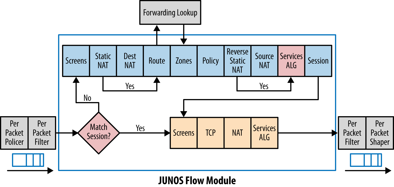
How Firewalls (Security Gateways) Handle the Packets? (Traffic Flow) , for Juniper SRX firewall Routing Lookup happens before policy.
In this case, before vpn policy is able to get packets into vpn tunnel , the packets went out firewall fxp0.0 interface by default route.
admin@fw2#
run show routeinet.0: 9 destinations, 10 routes (9 active, 0 holddown, 0 hidden)
+ = Active Route, - = Last Active, * = Both
0.0.0.0/0 *[Static/5] 1d 06:08:38 > to 10.99.12.1 via fxp0.010.99.12.0/24 *[Direct/0] 1d 06:08:38 > via fxp0.0 [Direct/0] 1d 06:08:38 > via fxp0.010.99.12.10/32 *[Local/0] 1d 06:08:38 Local via fxp0.010.99.12.15/32 *[Local/0] 1d 06:08:38 Local via fxp0.010.99.132.0/24 *[Direct/0] 1d 06:08:38 > via reth0.010.99.132.18/32 *[Local/0] 1d 06:08:38 Local via reth0.010.99.136.0/24 *[Direct/0] 1d 06:08:38 > via reth1.010.99.136.18/32 *[Local/0] 1d 06:08:38 Local via reth1.0192.168.9.0/24 *[Static/5] 06:31:41 > to 10.99.132.1 via reth0.0Solutions:
At this moment, firewall only has one specific route for peer gateway. Another specific static route will be added to route interesting traffic through external interface.
admin@fw2# showstatic { route 0.0.0.0/0 next-hop 10.99.12.1; route 192.168.9.0/24 next-hop 10.99.132.1;}john@fw-m-pin-b# set static route 10.94.138.0/24 next-hop 10.99.132.1After added this route, tunnel is up right away when testing with interesting traffic.
{primary:node1}
john@fw-m-pin-b>
show security ike security-associationsnode1:--------------------------------------------------------------------------Index State Initiator cookie Responder cookie Mode Remote Address 11102161 UP 5184a7627510f777 bba6d0242cb15a30 Main 192.168.9.18 admin@fw2>
show security ipsec security-associations node1:-------------------------------------------------------------------------- Total active tunnels: 1 ID Algorithm SPI Life:sec/kb Mon lsys Port Gateway <2 ESP:aes-128/sha256 1cca52a5 3567/ unlim - root 500 192.168.9.18 >2 ESP:aes-128/sha256 30b03088 3567/ unlim - root 500 192.168.9.18 Reference:
1.
Using PKI Build Route-Based IPSec VPN between Juniper SRX2.
Configuration Examples: Policy-based VPN