Pages

Wednesday, June 22, 2016

Fortigate 60D High Availability Configuration Steps

Fortigate 60D has been used to do HA examples in this post.

The back of Fortigate 60D:


The configuration steps for Fortigate High Availability is the easiest one comparing other firewall vendors. Fortigate cookbook "High Availability with two FortiGates" has presented enough detailed steps for most situations. In this post, it records the steps I just recently did.

Topology:


WAN1 is connecting to External switch then connected to Internet.
LAN port 1 is connecting to Internal switch.

Both DMZ and WAN2 ports are used as HA heartbeat interface. Two regular Ethernet cables are connecting them together as show in the following photo:

 
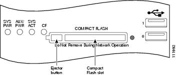
After device powed on, the front panel looks like below:


Configuration steps:

1. Start with Primary which is running at standalone mode and has configured all interfaces and policy.

1. 1 Change the primary first from standalone to Active-passive mode.
1.2 Set the priority between 1 and 255. Since it is primary, I set it to 250.
1.3 type HAGroup1 as the HA group name and enter a password for this group.
1.4 Choose DMZ and WAN2 as Heartbeat Interfaces.

2. Add new Fortigate 60D as secondary device. 

Since it is new, you will not need to do any configuration. 
2.1 Change the secondary Fortigate 60D from standalone mode to Active-passive mode.
2.2 Set the priority between 1 and 255. Since it is secondary, I set it to 50.
2.3 type HAGroup1 as the HA group name and enter a password for this group.
2.4 Choose DMZ and WAN2 as Heartbeat Interfaces.

3. Verify

After the configuration completed, you should be able to see both Fortigate 60D in the list. One is master and another is slave.

All configuration will be synchronised from Primary to Secondary through Heartbeat interfaces. 


Notes: To make both devices HA configuration running well, you will need to make sure following requirements met;
  • Same hardware
  • Same FortiOS version
  • License for some special features
  • LAN Switch mode (Switch / Interface)


Manual Failover Test Command:
diagnose sys ha reset-uptime
Upgrade Procedures:
To upgrade the firmware without interrupting communication through the cluster, the cluster goes through a series of steps that involve first upgrading the firmware running on the subordinate units, then making one of the subordinate units the primary unit, and finally upgrading the firmware on the former primary unit. These steps are transparent to the user and the network, but depending upon your HA configuration may result in the cluster selecting a new primary unit.
From the FortiGate web‑based manager go to System > Dashboard > Status. In the System Information widget, the Firmware Version will show the updated version of FortiOS (or from the CLI enter get system status).


Reference:


Friday, June 17, 2016

Basic Fortinet Firewall Fortigate CLI Commands (Tips and Tricks)

1. FGT30D # config system interface 


FGT30D (interface) # show
config system interface
edit "wan"
set ip 10.99.142.1 255.255.255.0
set allowaccess ping https ssh snmp http fgfm
set type physical
set snmp-index 2
next
.....
edit "lan"
set ip 192.168.100.1 255.255.255.0
set allowaccess ping https ssh http fgfm capwap
set type physical
set snmp-index 1
next
end

2. Change System Hostname

FGT30D # config system global 
FGT30D (global) # set hostname FGT30D
FGT30D (global) # end


3. Configure System DHCP Server 

on Interface "lan":

FGT30D # config system dhcp server 
config system dhcp server
    edit 1
        set default-gateway 192.168.100.1
        set dns-service default
        set interface "lan"
            config ip-range
                edit 1
                    set end-ip 192.168.100.200
                    set start-ip 192.168.100.80
                next
            end
        set netmask 255.255.255.0
    next
end

4. Configure Firewall Policy

FGT30D # config firewall policy 

config firewall policy 
    edit 1
        set srcintf "lan"
        set dstintf "wan"
        set srcaddr "all"
        set dstaddr "all"
        set action accept
        set schedule "always"
        set service "ALL"
        set nat enable
    next
end

5. Configure static gateway

FGT30D # config router static 

config router static
    edit 1
        set device "wan"
        set gateway 10.99.142.6
    next
end


FGT30D3X1401796 $ conf router static
FGT30D3X1401796 (static) $
edit 2
new entry '2' added
FGT30D3X1401796 (2) $
set device "lan"
FGT30D3X1401796 (2) $
set dst 10.9.9.0 255.255.255.0
FGT30D3X1401796 (2) $
set gateway 10.9.13.1
FGT30D3X1401796 (2) $
end


6. Configure system DNS host

FGT30D # config system dns 
config system dns
    set primary 208.91.112.53
    set secondary 208.91.112.52
end

7. Set System Users

FGT30D # config system admin
config system admin
edit admin
set password <psswrd>
config system admin
    edit "admin"
        set accprofile "super_admin"
 ....
        set password ENC AK1TDEt3tvzlnXWgK7ZjkFDgEisgltyWyK2/lnOYtvcl28=
    next
    edit "superadmin1"
        set accprofile "super_admin"
....
        set password ENC AK1eDVLPbT+qARqmQ5r0ituEhnmu9xVwdAbo2puf9TZofo=
    next
    edit "testadmin"
        set accprofile "prof_admin"
        set password ENC AK1JB0gM4GKvhld20nMmfFbhnictGo/+oUIqAaGTGlb+vg=
    next
end

8. Configure Syslog Settings

config log syslogd(2|3) setting
set status enable
set server 10.99.1.1
set port 514
set facility user
end
diagnose log test // Test logging

9. Execure Command - Ping


FGT30D # execute ping www.google.ca
PING www.google.ca (173.194.46.111): 56 data bytes
64 bytes from 173.194.46.111: icmp_seq=0 ttl=57 time=20.7 ms
64 bytes from 173.194.46.111: icmp_seq=1 ttl=57 time=22.7 ms
64 bytes from 173.194.46.111: icmp_seq=2 ttl=57 time=20.6 ms
--- www.google.ca ping statistics ---
3 packets transmitted, 3 packets received, 0% packet loss
round-trip min/avg/max = 20.6/21.3/22.7 ms

Set Ping Source:

FGT30D # execute ping-options source 192.168.1.1
FGT30D # execute ping-options viewPing Options:
Repeat Count: 5
Data Size: 56
Timeout: 2
Interval: 1
TTL: 64
TOS: 0
DF bit: unset
Source Address: 192.168.1.1
Pattern:
Pattern Size in Bytes: 0
Validate Reply: no
Note: ping-options will reset when session closed


10. Time Out Configuration


FGT30D3X13001834 # show system session-ttl
config system session-ttl
    set default 30000
        config port
            edit 23
                set timeout 72000
            next
        end
end

11. Debugging 


diag debug enable
diag debug console timestamp enable
diag sniffer packet wan 'host 8.8.8.8' 1
diag debug disable
diag debug reset

12. Backup/Restore Configuration to Flash


FGT30D #
execute backup config flash
Please wait...
Config backed up to flash disk done.
Setting timestamp
FGT30D #
execute revision list config
Last Firmware Version: V0.0.0-build000-REL0
ID TIME ADMIN FIRMWARE VERSION COMMENT
1 2015-02-10 13:39:29 jn V5.0.0-build292-REL0
2 2015-02-10 13:42:15 jn V5.0.0-build292-REL0 20140210


Restore Configuration from Flash:

FGT30D # execute restore config flash
<revision> Revision ID on the flash.

FGT30D #
execute restore config flash 2
This operation will overwrite the current settings!
Do you want to continue? (y/n)y
Please wait...
Get config from local disk OK.
File check OK.


13. Get system configuraiton
get system arp          // ARP Table
get system dns // DNS Configuration
get system dhcp server // DHCP server configuration

FGT30D # get system setting
opmode              : nat
firewall-session-dirty: check-all
bfd                 : disable
utf8-spam-tagging   : enable
wccp-cache-engine   : disable
vpn-stats-log       :
vpn-stats-period    : 0
v4-ecmp-mode        : source-ip-based
gui-default-policy-columns:
asymroute           : disable
ses-denied-traffic  : disable
strict-src-check    : disable
asymroute6          : disable
per-ip-bandwidth    : disable
sip-helper          : enable
sip-nat-trace       : enable
status              : enable
sip-tcp-port        : 5060
sip-udp-port        : 5060
sccp-port           : 2000
multicast-forward   : enable
multicast-ttl-notchange: disable
allow-subnet-overlap: disable
deny-tcp-with-icmp  : disable
ecmp-max-paths      : 10
discovered-device-timeout: 28
email-portal-check-dns: enable 
show system interface wan1 | grep -A2 ip // Show WAN and interface information.
get system info admin status // Show logged in users
get system status // Show system hardware/software update versions
get hardware status // Detailed hardware model information
get system performance status   // Check System Uptime


FGT30D3X12001671 $
get system performance status
CPU states: 0% user 0% system 0% nice 100% idle
CPU0 states: 0% user 0% system 0% nice 100% idle
Memory states: 21% used
Average network usage: 3 kbps in 1 minute, 0 kbps in 10 minutes, 0 kbps in 30 minutes
Average sessions: 14 sessions in 1 minute, 11 sessions in 10 minutes, 11 sessions in 30 minutes
Average session setup rate: 0 sessions per second in last 1 minute, 0 sessions per second in last 10 minutes, 0 sessions per second in last 30 minutes
Virus caught: 0 total in 1 minute
IPS attacks blocked: 0 total in 1 minute
Uptime: 106 days, 0 hours, 8 minutes

get system performance top
show system interface 
diagnose hardware deviceinfo nic // Interface Statistics/Settings
diagnose hardware sysinfo memory
diag debug crashlog read
diag hardware sysinfo shm // Device should be in 0, if (>0) then conservemode
get system global | grep -i timer // Show tcp and udp timers for halfopen and idle
get system session-ttl // System default tcp-idle session timeout
get hardware nic
get system interface physical
diagnose ip address list
diagnose ip arp list
diagnose sys session list
diagnose sys session clear
diagnose sys kill 9 <id>


14. Change Bult-in Internal Switch to Interface mode

In Switch mode, all the internal interfaces are part of the same subnet and treated as a single interface, called either lan or internal by default, depending on the FortiGate model. Switch mode is used when the network layout is basic, with most users being on the same subnet.

In Interface mode, the physical interfaces of the FortiGate unit are handled individually, with each interface having its own IP address. Interfaces can also be combined by configuring them as part of either hardware or software switches, which allow multiple interfaces to be treated as a single interface.

a. Command to change the FortiGate to switch mode:
config system global
         set internal-switch-mode switch
end
b. Command to change the FortiGate to interface mode:
config system global
         set internal-switch-mode interface
end

After changed internal switch from switch mode to interface mode, you will be able to move some interface out of Internal switch and they will become routing interfaces for you to do configuration.


Here is a user case. HA implementation will need two routing ports. If you change your switch to interface mode, you will be able to use two LAN ports for HA purpose.


Note: How to Change Switch Mode to Interface Mode in Fortigate FortiOS 5


15. Reset System to Factory 


FGT60D # execute factoryreset 
This operation will reset the system to factory default!
Do you want to continue? (y/n)y


System is resetting to factory default...


The system is going down NOW !!
FGT60D #
Please stand by while rebooting the system.
Restarting system.


FortiGate-60D (10:49-11.12.2014)
Ver:04000024
Serial number: FGT60D4P14005710
CPU(00): 800MHz
Total RAM:  2GB
Initializing boot device...
Initializing MAC... nplite#0
Please wait for OS to boot, or press any key to display configuration menu......

Booting OS...
Reading boot image... 1278067 bytes.
Initializing firewall...

System is starting...


16. Daily System Scheduled Reboot


config system global
set daily-restart enable
set restart-time 05:06
end


Note: For weekly reboot, you will need expect command with a script.


17. Check Interface Status (Speed / Duplex)

FGT30D3X1502126 $ get system interface physical
== [onboard]
==[lan]
mode: static
ip: 10.9.14.8 255.255.255.0
ipv6: ::/0
status: up
speed: 1000Mbps (Duplex: full)
==[wan]
mode: static
ip: 10.9.16.8 255.255.255.0
ipv6: ::/0
status: up
speed: 1000Mbps (Duplex: full)
==[modem]
mode: pppoe
ip: 0.0.0.0 0.0.0.0
ipv6: ::/0
status: down
speed: n/a

FGT30D3X1502126 $
get hardware nic lan
Driver Name :Fortinet NP4Lite Driver
Version :1.0.1
Admin :up
Current_HWaddr 90:6c:ac:13:45:88
Permanent_HWaddr 90:6c:ac:13:45:88
Status :up
Speed :1000
Duplex :Full
Host Rx Pkts :1252679
Host Rx Bytes :91142924
Host Tx Pkts :88665
Host Tx Bytes :11744688
Rx Pkts :1211790
Rx Bytes :106073828
Tx Pkts :75589
Tx Bytes :111560468
rx_buffer_len :2048
Hidden :No
cmd_in_list : 0
promiscuous : 1

FGT30D3X1502126 $ diag netlink interface list lan

if=lan family=00 type=1 index=3 mtu=1500 link=0 master=0
ref=16 state=start present fw_flags=8000 flags=up broadcast run allmulti multicast
Qdisc=pfifo_fast hw_addr=90:6c:ac:13:45:88 broadcast_addr=ff:ff:ff:ff:ff:ff
stat: rxp=1218030 txp=75593 rxb=106620201 txb=111560708 rxe=0 txe=0 rxd=0 txd=0 mc=0
collision=0
re: rxl=0 rxo=0 rxc=0 rxf=0 rxfi=0 rxm=0
te: txa=0 txc=0 txfi=0 txh=0 txw=0
misc rxc=0 txc=0 stop=0
input_type=0 state=6 arp_entry=5 refcnt=16


19.Time and Date, or NTP

To configure NTP via the CLI
To synchronize with an NTP server, enter the following commands:
config system global
set ntpsync enable
set timezone <timezone_index>
set ntpserver {<server_fqdn> | <server_ipv4>}
end

To manually set the date and time via the CLI
To manually configure the FortiWeb appliance’s system time and disable the connection to an NTP server, enter the following commands:
config system global
set ntpsync disable
set timezone <timezone_index>
set dst {enable | disable}
end
execute time 12:03:01
execute date 2016-10-09


20. Some HA Commands

Manual Failover HA

diagnose sys ha reset-uptime


Mange Cluster Member from Console
Test-1 # get system ha status 
Model: FortiGate-60D
Mode: a-p
Group: 0
Debug: 0
ses_pickup: disable
Master:250 Test-1 FGT60D4614041798
1
Slave : 50 Test-2 FGT60D4Q15005710
0
number of vcluster: 1
vcluster 1: work 169.254.0.2
Master:0 FGT60D4614041798
Slave :1 FGT60D4Q15005710

Test-1 #
execute ha manage 0

Test-2 $

Test-2 $
execute reboot
This operation will reboot the system !
Do you want to continue? (y/n)y


Configuration Example

Fortigate Device Information:
LAN : 192.168.200.1/24
WAN : 85.86.87.2/29
Default Gateway to ISP: 85.86.87.1


config system global
# Set the http admin port to 80/tcp
set admin-port 80
# Set the https admin port to 443/tcp
set admin-sport 443
# Set the ssh admin port to 22/tcp
set admin-ssh-port 22
# Set the telnet admin port to 23/tcp
set admin-telnet-port 23
# Set the hostname
set hostname “FW-Office-1”
# Set the ntp server to “0.ca.pool.ntp.org” and enable it
set ntpserver “0.ca.pool.ntp.org”
set ntpsync enable
# Set to 43200 seconds the tcp-halfclose timer
set tcp-halfclose-timer 43200
end
# Set the telnet 23/tcp port timeout to 43200 seconds.
config system session-ttl
set default 43200
config port
edit 23
set timeout 43200
next
end
# Set the IP address and administrative access options (ping https http) for lan interface.
config system interface
edit “lan”
set ip 192.168.200.1 255.255.255.0
set allowaccess ping https http
set type physical
next
# Set the IP address and administrative access options (ping https) for wan interface.
# Set “gateway Detect” option enable and set the “Ping Server” destination.
# Set the interface speed to 10 Mb/s Half Duplex, this is useful for some connections like radio bridge.
edit “wan1″
set ip 85.86.87.2 255.255.255.248
set allowaccess ping https
set gwdetect enable
set detectserver “85.86.87.23″
set type physical
set speed 10half
next
end
# Set DNS Servers and DNS options
config system dns
set primary 192.168.200.3
set secondary 8.8.8.8
set domain ”
set autosvr disable
set dns-cache-limit 5000
set cache-notfound-responses disable
end
# Set a firewall policy to enable traffic from lan TO WAN using NAT
# Set a protection profile (a default one) called “scan”
config firewall policy
edit 1
set srcintf “lan”
set dstintf “wan″
set srcaddr “all”
set dstaddr “all”
set action accept
set schedule “always”
set service “ANY”
set profile-status enable
set profile “scan”
set nat enable
next
end
# Set a default gateway on the WAN interface
config router static
edit 1
set device “wan″
set gateway 85.86.87.1
end


Reference:

Online Demo Read Access for Fortinet Products

  • Fortigate:
user:demo
password: demo
fortigate.com
  • ForiAnalyzer:
user:demo
password: demo
fortianalyzer.com
  • FortiManager:
user:demo
password: demo
fortimanager.com
  • FortiMail
user:demo
password: demo
https://209.87.230.132/admin
  • FortiWeb
user:demo
password: demo
http://fortiweb.fortinet.com/
  • FortiDB
user:demo
password: demo
http://www.fortidb.com/

Forticloud


Online Resources


Tuesday, June 14, 2016

Windows Network Policy Server Basic Radius Configuration for Cisco devices

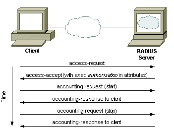
RADIUS Traffic 

RADIUS server configuration on Cisco IOS is performed in two steps, one set of commnads are defined within the AAA paradigm and other set is run with the “radius” commands. The aaa configurations on the Cisco IOS needs to be done with named method lists or the default list can be used. The simplest way to start with the configurations is to use the built-in default method lists.


1. Configuration on Cisco Switches and Routers


Table 1.       AAA Configuration for RADIUS
Command
Description
aaa new-model
Enable Authentication Authorization and Accounting (AAA)
aaa authentication login default group radius local
activate authentication for logins to the router and specify that RADIUS is the preferred method but we’ll include the local user database as a fall back if RADIUS becomes unavailable.  Note that users in the local database cannot be used if the user doesn’t exist in RADIUS, it will only fall back if the RADIUS server is offline.
aaa authorization exec default group radius if-authenticated
This command is optional but will automatically take RADIUS authenticated users to privileged Exec (15) mode without requiring them to type “enable”.
aaa authentication enable default enable group radius 
issue authentication to get to enable mode (privilege 15).. Only the password will be requested, the username is $enab15$. Hence the username $enab15$ must be defined on the AAA server. If the Radius server doesn't reply, the enable password configured locally on the router will have to be entered
aaa authentication login CONSOLE local
To have console access authenticated by a local username and password,
Table 2.       RADIUS Server Configuration
Command
Description
radius server <name>
Specifies the name for the RADIUS server configuration and enters RADIUS server configuration mode.
address ipv4 X.X.X.X auth-port
<0-65535> acct-port <0-65535>
Configures the IPv4 address for the RADIUS server accounting and authentication parameters.
key <shared-secret>
The shared secret key that’s configured on the RADIUS server must be defined for secure RADIUS communications.
ip radius source-interface <interface>
To force RADIUS to use the IP address of a specified interface for all outgoing RADIUS packets, use the ip radius source-interface command in global configuration mode. The source IP address of the RADIUS packets must match the NAS IP address configured on the RADIUS server. A mismatch leads to RADIUS packet timeout and the server gets marked “DEAD”.


!!! Traditional way to configure a radius server on a cisco IOS device:
aaa authentication login default local group radius group tacacs+
aaa authentication enable default enable group radius group tacacs+
aaa authorization exec default local group radius group tacacs+
aaa authorization console

radius-server host 10.9.2.14 auth-port 1812 acct-port 1646 key cisco1234


!!!==================================================================
!!! Group configuration
aaa group server radius GrpRadius
 server-private 10.9.1.91 key cisco1234
aaa authentication login default local group GrpRadius
aaa authentication enable default enable group GrpRadius
aaa authorization exec default local group GrpRadius
aaa authorization console


!!!===================================================================


ip radius source-interface Vlan254

line vty 0 15
authorization exec default
login authentication default

line con 0
authorization exec default

login authentication default


Note:    RADIUS has been officially assigned UDP ports 1812 for RADIUS authentication and 1813 for RADIUS accounting by the Internet Assigned Numbers Authority (IANA). However, prior to IANA allocation of ports 1812 and 1813, ports 1645 and 1646 (authentication and accounting, respectively) were used unofficially, and became the default ports assigned by many RADIUS client/server implementations at that time. The tradition of using 1645 and 1646 for backwards compatibility continues to this day. For this reason, many RADIUS server implementations monitor both sets of UDP ports for RADIUS requests.


2. NPS Configuration

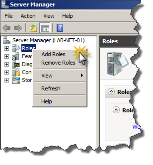
First step is to install NPS on Windows Server 2008 or 2012 R2. In order to do that Server Manager has to be used. In Server Manager right-click on Roles and choose Add Roles from context menu.

  1. Create a new Windows Server 2008 R2 or Windows Server 2012 machine
  2. Add the machine to the domain
  3. Give the machine a static IP: (I’ll use 10.10.10.15 throughout this document as a reference to this server)
  4. Open up Server Manager, click Add Roles, click Next on the Before You Begin screen, check Network Policy and Access Services and click Next, click Next on the Introduction screen, check Network Policy Server (leave the rest unchecked) and click Next, clickInstall.
  5. Once Network Policy Server is installed, launch the Network Policy Server snap-in (via MMC or Administrative Tools)

More installation steps detail you can get it from this post.

2.1 Create Radius Clients for all of your switches and routers which will use your Radius NPS authentication.


2.2 Create a new Network Policy


Specify which AD group will be used to do authentication.


On Configure Authentication Methods make sure that Unencrypted authentication (PAP, SPAP) checkbox is checked.
Create a new Service Type - Login
The users' login access is controlled on the NPS.
The Vendor specific attribute controls that part.
shell:priv-lvl=15  gives the Level 15
  • privilege level 1 = non-privileged (prompt is router>), the default level for logging in
  • privilege level 15 = privileged (prompt is router#), the level after going into enable mode
  • privilege level 0 = seldom used, but includes 5 commands: disableenableexithelp, and logout


Reference:


Friday, June 3, 2016

Password Recovery for Cisco Router 2900


I have to reset one Cisco 2901 router to factory default. Unfortunately no one knows user name and password.

Cisco documentation Password Recovery Procedure for the Cisco 2900 Integrated Services Router has listed all steps, but not enough detail how to "Remove the compact flash that is on the rear of the router."

I understand Cisco 2900 series is using a different way to do password recovery than a usual way by press 'Break' key during booting process. Cisco 2900 will automatically boot into ROMMOM mode after you removed Compact Flash card. But how to remove CF card from the rear of router, it does not say enough from Password Recovery Procedure for the Cisco 2900 Integrated Services Router.

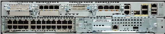
Here are what I figured out by using a flat head screw driver. Lets find out where the compact flash card locates from following photo:


There are two CF slots. The right one is 0 which usually holds CF inside.

Before you process to remove CF slot cover, turn off your router first.

Using a flat head screwdriver to plug into the cover spring place as show in the next photo, slightly push and pry it a bit to left. The CF slot cover can be lifted out. After removed the cover, you will see CF is securely plugged inside. Taking CF card out will be quite easy now.


Basic steps to do 2900 router's password recovery.

After boot into ROMMON mode, change config-register value to 0x2142 to ignore startup-configuration during next boot process.

Press RETURN to get started.


System Bootstrap, Version 15.0(1r)M9, RELEASE SOFTWARE (fc1)
Technical Support: http://www.cisco.com/techsupport
Copyright (c) 2010 by cisco Systems, Inc.

Total memory size = 512 MB - On-board = 512 MB, DIMM0 = 0 MB
CISCO2901/K9 platform with 524288 Kbytes of main memory
Main memory is configured to 72/-1(On-board/DIMM0) bit mode with ECC enabled


Readonly ROMMON initialized
Compact Flash0: Not present

System Bootstrap, Version 15.0(1r)M9, RELEASE SOFTWARE (fc1)
Technical Support: http://www.cisco.com/techsupport
Copyright (c) 2010 by cisco Systems, Inc.

Total memory size = 512 MB - On-board = 512 MB, DIMM0 = 0 MB
CISCO2901/K9 platform with 524288 Kbytes of main memory
Main memory is configured to 72/-1(On-board/DIMM0) bit mode with ECC enabled


Readonly ROMMON initialized
Compact Flash1: Not present

System Bootstrap, Version 15.0(1r)M9, RELEASE SOFTWARE (fc1)
Technical Support: http://www.cisco.com/techsupport
Copyright (c) 2010 by cisco Systems, Inc.

Total memory size = 512 MB - On-board = 512 MB, DIMM0 = 0 MB
CISCO2901/K9 platform with 524288 Kbytes of main memory
Main memory is configured to 72/-1(On-board/DIMM0) bit mode with ECC enabled


Readonly ROMMON initialized
Compact Flash0: Not present

System Bootstrap, Version 15.0(1r)M9, RELEASE SOFTWARE (fc1)
Technical Support: http://www.cisco.com/techsupport
Copyright (c) 2010 by cisco Systems, Inc.

Total memory size = 512 MB - On-board = 512 MB, DIMM0 = 0 MB
CISCO2901/K9 platform with 524288 Kbytes of main memory
Main memory is configured to 72/-1(On-board/DIMM0) bit mode with ECC enabled


Readonly ROMMON initialized
rommon 1 > confreg 0x2142


You must reset or power cycle for new config to take effect
rommon 2 > reset

System Bootstrap, Version 15.0(1r)M9, RELEASE SOFTWARE (fc1)
Technical Support: http://www.cisco.com/techsupport
Copyright (c) 2010 by cisco Systems, Inc.

Total memory size = 512 MB - On-board = 512 MB, DIMM0 = 0 MB
CISCO2901/K9 platform with 524288 Kbytes of main memory
Main memory is configured to 72/-1(On-board/DIMM0) bit mode with ECC enabled


Readonly ROMMON initialized
program load complete, entry point: 0x80803000, size: 0x1b340


IOS Image Load Test
___________________
Digitally Signed Release Software
program load complete, entry point: 0x81000000, size: 0x3bc7164
Self decompressing the image : ##################################################
###########################################################################
###########################################################################
###########################################################################
###########################################################################
######################## [OK]

Smart Init is enabled
smart init is sizing iomem
                 TYPE      MEMORY_REQ
          HWIC Slot 0      0x00200000
          HWIC Slot 1      0x00200000
          HWIC Slot 2      0x00200000
    Onboard devices &
         buffer pools      0x0228F000
-----------------------------------------------
               TOTAL:      0x0288F000

Rounded IOMEM up to: 44Mb.
Using 8 percent iomem. [44Mb/512Mb]

              Restricted Rights Legend

Use, duplication, or disclosure by the Government is
subject to restrictions as set forth in subparagraph
(c) of the Commercial Computer Software - Restricted
Rights clause at FAR sec. 52.227-19 and subparagraph
(c) (1) (ii) of the Rights in Technical Data and Computer
Software clause at DFARS sec. 252.227-7013.

           cisco Systems, Inc.
           170 West Tasman Drive
           San Jose, California 95134-1706


Cisco IOS Software, C2900 Software (C2900-UNIVERSALK9-M), Version 15.0(1)M4, RELEASE SOFTWARE (fc1)
Technical Support: http://www.cisco.com/techsupport
Copyright (c) 1986-2010 by Cisco Systems, Inc.
Compiled Thu 28-Oct-10 18:32 by prod_rel_team
Image text-base: 0x2100E358, data-base: 0x2593FA80


This product contains cryptographic features and is subject to United
States and local country laws governing import, export, transfer and
use. Delivery of Cisco cryptographic products does not imply
third-party authority to import, export, distribute or use encryption.
Importers, exporters, distributors and users are responsible for
compliance with U.S. and local country laws. By using this product you
agree to comply with applicable laws and regulations. If you are unable
to comply with U.S. and local laws, return this product immediately.

A summary of U.S. laws governing Cisco cryptographic products may be found at:
http://www.cisco.com/wwl/export/crypto/tool/stqrg.html

If you require further assistance please contact us by sending email to
export@cisco.com.

Cisco CISCO2901/K9 (revision 1.0) with 479232K/45056K bytes of memory.
Processor board ID FTX15110600
2 Gigabit Ethernet interfaces
3 Serial interfaces
DRAM configuration is 64 bits wide with parity enabled.
255K bytes of non-volatile configuration memory.
254464K bytes of ATA System CompactFlash 0 (Read/Write)


         --- System Configuration Dialog ---


Would you like to enter the initial configuration dialog? [yes/no]: n


After logged into enable mode, copy startup-config to running-config. You may get some warning messages, but they can be ignored.

Router#copy startup-config running-config
Destination filename [running-config]?

% Hostname "Test-Test-       " is not a legal LAT node name, Using "CISCO_4269D0"
*Jun  3 20:09:12: %SYS-6-CLOCKUPDATE: System clock has been updated from 20:09:12 UTC Fri Jun 3 2016 to 20:09:12 GMT Fri Jun 3 2016, configured from console by console.
*Jun  3 20:09:13: %LINEPROTO-5-UPDOWN: Line protocol on Interface Loopback0, changed state to up
% Warning: use /31 mask on non point-to-point interface cautiously
%Error: This command applies only to DCE interfaces

10112 bytes copied in 7.808 secs (1295 bytes/sec)


Change enable password and add a new user admin into configuration.
Change config-register to default 0x2102 to load start-up configuration during boot process

test-test-2183(config)#enable secret 0 admin
The enable secret you have chosen is the same as your enable password.

This is not recommended.  Re-enter the enable secret.
test-test-2183(config)#username admin privilege 15 password admin
test-test-2183(config)#config-register 0x2102


Reference: