Pages

Saturday, July 16, 2016

Check Point 1100 Appliance Configuration Step by Step

Check Point 1100 Appliance
A couple of months ago, I received Check Point 600 Appliance and did a post regarding basic configuration for 600. It is used to replace replaces the Save@Office models and cannot be managed centrally by a Check Point SmartCenter Server. 1100 appliance is an all-in-one security appliance that offers robust, multi-layered protection with branch offices in mind, including flexible network interfaces and a compact, desktop form factor, which is used to replace the SG80 and the UTM-1 Edge.

Both 600 and 1100 appliances support local management. The SG600 can be centrally managed by Check Point's SMB Management Cloud service. The SG1100 can be managed by standard Check Point management running R75.46 or above. Neither unit can be managed by the old Sofaware SMP product.


Back panel: 8 LAN ports, 1 WAN port, 1 DMZ port, console port.

Front Panel: there is one usb slot.


Configuration:
1. Connect One of LAN ports with your computer.
Your computer will get a DHCP ip address from 192.168.1.0/24 network.
In my case, my laptop got 192.168.1.126 ip address and gateway is 192.168.1.1 which is 1100 appliance's default LAN interface ip.

Type http://192.168.1.1 or https://192.168.1.1 , the browser will automatically re-direct to https://192.168.1.1:4434 , which is default management interface of Check Point 1100 appliance.


2. First Time Configuration Wizard 
It will guide you to complete basic configuration step by step.


3.  Log in 1100 Appliance


4. Firewall Access Policy Configuration


4.1 Static NAT Server Configuration


\


4.2 Outbound Internet Access Rule


4.3 Inbound Access Rule from Internet

In following screenshots, there are three parts:

  • Red rectangle part is Outgoing access to the Internet which is auto-generated rule from 4.2
  • Green rectangle part is Incoming rules and VPN rules
    • Yellow rectangle part is manual rules for inbound traffic
    • Blue rectangle part is those auto-generated rules from 4.1 by static server NAT configuration.


Reference:


Sunday, June 26, 2016

Cisco Wireless Controller 5508 Configuration Step by Step - Part 3 (Certs Auth and Other Settings)


This post will use a typical WiFi in office environment as an example to present related configuration on WLC, Radius (NPS), DHCP Servers.

1. Topology:

1.1 Network Topology


Relate Posts:

1.2 Device List:

  • Cisco AP 1702i
  • Switches
  • Radius Server - Microsoft NPS
  • DHCP Server
  • Cisco WLC5508


1.3 Topology for Wireless Access with Digital Certificate Client Authentication


2. WiFi Access Requirements
This WiFi  access is primarily intended for company laptops which already has client certificate installed on the machine through domain group policy. This WiFi network will be on a separate office VLAN from other office VLAN.

Other WiFi connected devices must not be allowed connecting to this office WiFi. They will connect through Company Guest WiFi. Mobile devices such as BYOD, Blackberry or other PDA and smart phones should not be allowed to connect to Office WiFi.


3. NPS Configuration

When using WPA2-Enterprise with 802.1x authentication EAP-TLS can be specified as an authentication method. When EAP-TLS is the chosen authentication method both the wireless client and the RADIUS server use certificates to verify their identities to each other and perform mutual authentication. Below are the steps for configuring policy in Windows Network Policy Server to support EAP-TLS. 
Creating a Connection Request Policy to support IEEE 802.11 wireless connections.
  1. Open the Network Policy Server console.
  2. Navigate to NPS(Local)>Policies>Connection Request Policies.
  3. Right click Connection Request Policies and select New.
  4. On Specify Connection Policy Name and Connection Type enter a Policy name: and click Next.
  5. On Specify Conditions click Add.
  6. Select NAS Port Type as a condition.
  7. For NAS Port Type check Wireless - IEEE 802.11 and Wireless - Other click OK.
  8. Click Next.
  9. On Specify Connection Request Forwarding leave the defaults and click Next.
  10. On Specify Authentication Methods leave the defaults and click Next.
  11. On Configure Settings click Next.
  12. Review the settings On Completing Connection Request Policy Wizard and click Finish
  13. Right click the Connection Policy created and select Move up so its processing order is before any other policies. 
Creating a Network Policy to support EAP-TLS as the authentication method for IEEE 802.11 wireless connections.

  1. Right click Network Policies and select New.
  2. On Specify Network Policy Name and Connection Type enter a Policy name: and click Next.
  3. On Specify Conditions click Add.
  4. Select NAS Port Type as a condition.
  5. For NAS Port Type check Wireless - IEEE 802.11 and Wireless - Other click OK.
  6. Click Next.
  7. On Specify Access Permissions make sure Access granted is selected and click Next.
  8. On Configure Authentication Methods click Add and choose Microsoft: Smart Card or other certificate for Add EAP and click OK.
  9. Uncheck any boxes under Less secure authentication methods.
  10. Select Microsoft: Smart Card or other certificate for EAP types and click Edit
  11. Verify the Certificate issued to: drop down shows the correct certificate and issuer which is the Active Directory CA server. Then click OK.
  12. Click Next.
  13. On Configure Constraints click Next.
  14. On Configure Settings choose NAP Enforcement.
  15. Under Auto-Remediation, uncheck the box Auto-remediation of client computers and click Next.
  16. Review the settings on Completing New Network Policy and Click Finish.
  17. Right click the Network Policy created and select Move up so its processing order is before any other policies. 

Here are screenshots for NPS Policy:


4. WLC Configuration


5. DHCP Option 43 configuration

When you are installing a Layer 3 access point on a different subnet than the Cisco wireless LAN controller, be sure that a DHCP server is reachable from the subnet on which you will be installing the access point, and that the subnet has a route back to the Cisco wireless LAN controller. Also be sure that the route back to the Cisco wireless LAN controller has destination UDP ports 5246 and 5247 open for CAPWAP communications. Ensure that the route back to the primary, secondary, and tertiary wireless LAN controller allows IP packet fragments. Finally, be sure that if address translation is used, that the access point and the Cisco wireless LAN controller have a static 1-to-1 NAT to an outside address. (Port Address Translation is not supported.)

You can use DHCP Option 43 to provide a list of controller IP addresses to the access points, enabling them to find and join a controller.

The access point must be able to find the IP address of the controller. This can be resolved by DHCP Option 43's configuration. 


option 43 hex <hex string>
The hex string is assembled by concatenating the TLV values shown below:
Type + Length + Value
Type is always f1(hex). Length is the number of controller management IP addresses times 4 in hex. Value is the IP address of the controller listed sequentially in hex.
For example, suppose that there are two controllers with management interface IP addresses, 10.126.126.2 and 10.127.127.2. The type is f1(hex). The length is 2 * 4 = 8 = 08 (hex). The IP addresses translate to 0a7e7e02 and 0a7f7f02. Assembling the string then yields f1080a7e7e020a7f7f02. The resulting Cisco IOS command added to the DHCP scope is option 43 hex f1080a7e7e020a7f7f0
IP Address to Hex Converter has a online converter to help you to convert IP address to Hex.


Reference:


Friday, June 24, 2016

Cisco Wireless Controller 5508 Configuration Step by Step - Part 2 (User/Machine Auth)


RADIUS server has been used on a Cisco® Catalyst switch, router or IOS based wireless controllers in the context of enterprise network access security.


1. 802.1x and EAP
While IEEE 802.1X enables authenticated access to IEEE 802 media, including Ethernet and 802.11 wireless LANs, the RADIUS infrastructure facilitates centralized Authentication, Authorization, and Accounting (AAA) management for users and devices that connect and use network service(s).


Relate Posts:
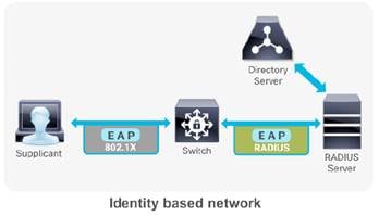
In an identity based network an endpoint (supplicant) initiates its network access session with a 802.1X authentication. The IEEE 802.1X access control protocol is fundamentally a layer 2 transport protocol that carries the Extensible Authentication Protocol (EAP) payload in it. EAP is an authentication framework that defines the transport and usage of identity credentials. EAP encapsulates the usernames, passwords, certificates, tokens, OTPs, etc. that a client sends for the purpose of authentication. The first hop Network Access Server (NAS) (switch/router/wireless controller), hands off the EAP payload to the authentication server via the RADIUS messaging. The RADIUS server either performs lookups with its internal user database or queries an external identiity store, and responds to the client accordingly with the appropriate authorization permissions.  The avaiability and servicability of a RADIUS server is fundamental for an enterprise grade secure access solution to operate.

To make wireless networks really secure you should use a RADIUS server to authenticate your users instead of using a pre-shared key. The RADIUS server will handle the authentication requests and uses EAP (Extensible Authentication Protocol) to communicate with users. There are many EAP types:

  • EAP (Extensible Authentication Protocol) uses an arbitrary authentication method, such as certificates, smart cards, or credentials.
  • EAP-TLS (EAP-Transport Layer Security) is an EAP type that is used in certificate-based security environments, and it provides the strongest authentication and key determination method.
  • EAP-MS-CHAP v2 (EAP-Microsoft Challenge Handshake Authentication Protocol version 2) is a mutual authentication method that supports password-based user or computer authentication.
  • PEAP (Protected EAP) is an authentication method that uses TLS to enhance the security of other EAP authentication protocols.


and the most popular ones are:

  • PEAP (Protected EAP)
  • EAP-TLS

PEAP is normally used to authenticate users by using a username and password. The RADIUS server will show a certificate to the users so that they can verify that they are talking to the correct RADIUS server. EAP-TLS is the most secure form of wireless authentication because it replaces the client username/password with a client certificate.

RADIUS is a distributed client/server system that secures networks against unauthorized access. It’s an open standard protocol that can be customized with vendor specific attributes.  In the Cisco implementation, RADIUS clients run on Cisco switches/routers/wireless controllers and send authentication requests to a central RADIUS server that contains all user authentication and network service access information. Cisco supports RADIUS under its AAA security paradigm. RADIUS can be used with other AAA security protocols, such as TACACS+, Kerberos, and local username lookup. RADIUS is supported on all Cisco platforms, but some RADIUS-supported features run only on specified platforms.


2. Configure Local EAP Authentication
Local EAP is an authentication method that allows users and wireless clients to be authenticated locally to WLC. This is useful for a remote branch where it does not have a external RADIUS on-site or do not want to rely on the WAN to connect back to main office RADIUS  or even that RADIUS server is gone down. Local EAP supports LEAP, EAP-FAST, EAP-TLS, PEAPv0/MSCHAPv2 and PEAPv1/GTC authentication between the WLC & wireless clients.

If any RADIUS servers are configured on the controller, the controller tries to authenticate the wireless client using the RADIUS servers  first. Local EAP is attempted only if no RADIUS servers found (timed out or no RADIUS configured).

2.1 Create local Net Users


2.2 Create a Local EAP Profie - 'localEAP-test'


2.3  Configure a WLAN in the controllers and specify Local EAP as authentication mechanism. 

Note that Radius authentication is disabled & only Local EAP selected.


After above steps, your wireless AP should be able to connect through local Net user authentication. You will make sure your this WLAN is in right vlan and on the switch vlan port, proper dhcp server / dhcp relay has been configued. Your connected wireless device will get ip address from your dhcp server.


3. Configure Authentication with AD

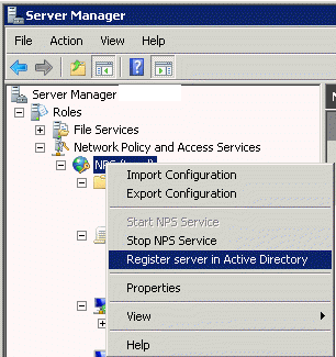
3.1 Register NPS server in AD

To enable Network Policy Server (NPS) to read user account information in Active Directory Domain Services (AD DS) during the authentication and authorization processes, you must register the server running NPS in AD.


3.2 Create a new Network Policy


3.3 Add a new condition

3.4 Select Windows Groups Condition

3.5 Choose a pre-defined domain user group


3.6 Choose Authentication methods


3.7 Choose some RADIUS attributes 

 
Notes:
Rather than using user group in step 3.4, you also can choose machine groups. It will require some change at client end.  You will have to change it from user or computer authentication to only computer authentication. The issue was caused by the Authentication Mode in the Security Settings for the Wireless Network Connection that we had setup in Group Policy (Computer Configuration > Windows Settings > Security Settings > Wireless Network (802.11) Policies > "Your Network Policy"). Originally the Authentication Mode was set to "User or Computer authentication", when this was changed to "Computer authentication" the Computer Account condition in the Network Policy in NPS was processed correctly and clients could connect. I can only assume that this is a bug as on further testing I found that when the Authentication Mode was set to "User or Computer authentication" NPS would process a User Account condition in the Network Policy correctly, but still refused to process the Computer Account condition properly.


Reference: