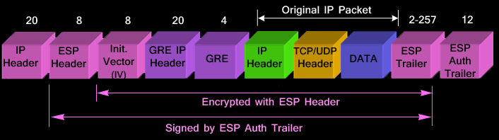
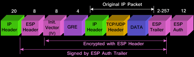
means Outer Header is GRE. In other words, IPSec is riding over GRE.
The order for IPsec over GRE is IPsec first, GRE second. This order will result in these operations:
The original header is obfuscated but not encrypted.
means Outer Header is IPSec.
1. IPSec Over GREExample 1:
Router1#show run
Building configuration...

Current configuration : 2063 bytes
!
! Last configuration change at 08:26:21 UTC Thu May 12 2011 by hari
!
version 15.0
service timestamps debug datetime msec
service timestamps log datetime msec
no service password-encryption
!
hostname Router1
!
boot-start-marker
boot-end-marker
!
!
aaa new-model
!
!
aaa authentication login default local
aaa authorization exec default local
!
!
aaa session-id common
!
!
!
ip source-route
!
ip cef
no ipv6 cef
!
multilink bundle-name authenticated
license udi pid CISCO892-K9 sn FGL151325XQ
!
!
username temp privilege 15 secret 5 $1$bTf6$BoInpDJHbBC1drvgr356h0
!
!
crypto isakmp policy 1
 encr 3des
 hash md5
 authentication pre-share
 group 2
crypto isakmp key cisco address 172.19.0.2
!
!
crypto ipsec transform-set myset esp-3des esp-sha-hmac
 mode transport
!
crypto map cmap 10 ipsec-isakmp
 set peer 172.19.0.2
 set transform-set myset
 match address 101
!
interface Loopback0
 ip address 1.1.1.1 255.255.255.255
 !
!
interface Tunnel0
 ip address 172.25.0.1 255.255.255.252
 tunnel source FastEthernet8
 tunnel destination 172.19.0.2
 tunnel path-mtu-discovery
 crypto map cmap
 !
!
interface BRI0
 no ip address
 encapsulation hdlc
 shutdown
 isdn termination multidrop
 !
!
interface FastEthernet0
 !
!
interface FastEthernet1
 !

.......
!
interface FastEthernet8
 ip address 172.19.0.1 255.255.255.0
 duplex auto
 speed auto
 !
!
interface GigabitEthernet0
 no ip address
 shutdown
 duplex auto
 speed auto
 !
!
interface Vlan1
 no ip address
 !
!
router ospf 1
 log-adjacency-changes
 network 1.1.1.1 0.0.0.0 area 0
 network 172.25.0.0 0.0.0.255 area 0
!
ip forward-protocol nd
no ip http server
no ip http secure-server
!
!
!
access-list 101 permit ip host 1.1.1.1 host 2.2.2.2
!
control-plane
 !
!
!
line con 0
line aux 0
line vty 0 4
 transport input telnet
line vty 5 193
 transport input telnet
!
scheduler max-task-time 5000
end
Router2#show run
Building configuration...

Current configuration : 1958 bytes
!
! Last configuration change at 02:44:36 UTC Mon May 2 2011
!
version 15.0
service timestamps debug datetime msec
service timestamps log datetime msec
no service password-encryption
!
hostname Router2
!
boot-start-marker
boot-end-marker
!
!
no aaa new-model
!
ip source-route
!
ip cef
no ipv6 cef
!
!
multilink bundle-name authenticated
license udi pid CISCO892-K9 sn FGL151324Y0
!
!
username hari privilege 15 secret 5 $1$JARP$69Wl2bZWX4fqfnoOIIFZn/
!
crypto isakmp policy 1
 encr 3des
 hash md5
 authentication pre-share
 group 2
crypto isakmp key cisco address 172.19.0.1
!
!
crypto ipsec transform-set myset esp-3des esp-sha-hmac
 mode transport
!
crypto map cmap 10 ipsec-isakmp
 set peer 172.19.0.1
 set transform-set myset
 match address 101
!
interface Loopback0
 ip address 2.2.2.2 255.255.255.255
 !
!
interface Tunnel0
 ip address 172.25.0.2 255.255.255.252
 tunnel source FastEthernet8
 tunnel destination 172.19.0.1
 tunnel path-mtu-discovery
 crypto map cmap
 !
!
interface BRI0
 no ip address
 encapsulation hdlc
 shutdown
 isdn termination multidrop
 !
!
interface FastEthernet0
 !
!.....
!
interface FastEthernet7
 !
!
interface FastEthernet8
 ip address 172.19.0.2 255.255.255.0
 duplex auto
 speed auto
 !
!
interface GigabitEthernet0
 no ip address
 shutdown
 duplex auto
 speed auto
 !
!
interface Vlan1
 no ip address
 !
!
router ospf 1
 log-adjacency-changes
 network 2.2.2.2 0.0.0.0 area 0
 network 172.25.0.0 0.0.0.255 area 0
!
ip forward-protocol nd
no ip http server
no ip http secure-server
!
!
!
access-list 101 permit ip host 2.2.2.2 host 1.1.1.1
!
control-plane
 !
!
!
line con 0
line aux 0
line vty 0 4
 login
 transport input telnet
line vty 5 193
 login
 transport input telnet
!
scheduler max-task-time 5000
end
https://supportforums.cisco.com/discussion/11190806/gre-over-ipsec
Trying to establish vpn session between 2 Cisco 892/k9 routers. but when i apply the crypto map in the GRE tunnel interface this type of message apears. NOTE: crypto map is configured on tunnel interface.
Currently only GDOI crypto map is supported on tunnel interface.
Suggestions:
If you are trying to configure GRE over IPSec, then you can do this with one of the 2 configuration options, 1) using crypto map and apply the crypto map to the physical egress interface for the GRE encapsulated tunnel packets,
2) using ipsec profiles with tunnel protection. With crypto map on the tunnel interface, the order of encapsulation is the opposite of what you are trying to do - it'll be encryption first and then tunnel encapsulation, in other words, it'll be IPSec over GRE. Currently we only support GETVPN with that, hence the warning you saw.Solution:
If there are reasons why you can not put a crypto map on the physical interface then I agree with the original suggestion by Wen and suggested again by Tod that you use the tunnel protection profile which will allow the tunnel to do GRE protected by IPSec and does not require crypto map.Are you configuring a Virtual Tunnel Interface with IP Security?
crypto isakmp policy 1
encr 3des
authentication pre-share
group 2
crypto isakmp key ******** address 0.0.0.0 0.0.0.0
crypto isakmp keepalive 10
!
!
crypto ipsec transform-set TSET esp-3des esp-sha-hmac
!
crypto ipsec profile VTI
set transform-set TSET
!
!
interface Tunnel0
ip address 192.168.10.2 255.255.255.0
tunnel source 10.0.149.220
tunnel destination 10.0.149.221
tunnel mode ipsec ipv4
tunnel protection ipsec profile VTI
========================================================================
Example 2:
SITE A:Local LAN: 192.168.1.254/255.255.255.0
Tunnel64: 10.0.64.1/255.255.255.0
interface Tunnel64
 description testing tunnel
 ip address 10.0.64.1 255.255.255.0
 ip mtu 1352
 ip tcp adjust-mss 1312
 tunnel source FastEthernet4
 tunnel destination (SITE B Public IP)
 tunnel path-mtu-discovery
 tunnel protection ipsec profile (VPN-PROFILE)
ip route 0.0.0.0 0.0.0.0 (ROUTER IP ADDRESS)
ip route 192.168.64.0 255.255.255.0 10.0.64.254
SITE B:
Local LAN: 192.168.64.254/255.255.255.0
Tunnel1: 10.0.64.254/255.255.255.0
interface Tunnel1
 ip address 10.0.64.254 255.255.255.0
 ip mtu 1352
 ip tcp adjust-mss 1312
 tunnel source FastEthernet4
 tunnel destination (SITE A Public IP)
 tunnel path-mtu-discovery
 tunnel protection ipsec profile (VPN PROFILE)
ip route 0.0.0.0 0.0.0.0 (PUBLIC IP GATEWAY)
ip route 192.168.1.0 255.255.255.0 10.0.64.1
https://supportforums.cisco.com/discussion/12345601/gre-over-ipsec-can-ping-tunnel-interface-not-remote-lan
=======================================================================
2. GRE over IPSecScenario 9
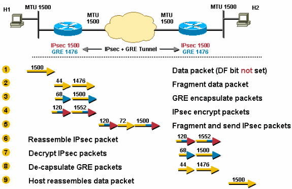
IPsec is deployed on top of GRE. The outgoing physical MTU is 1500, the IPsec PMTU is 1500, and the GRE IP MTU is 1476 (1500 - 24 = 1476). Because of this, TCP/IP packets will be fragmented twice, once before GRE and once after IPsec. The packet will be fragmented before GRE encapsulation and one of these GRE packets will be fragmented again after IPsec encryption.
Configuring "ip mtu 1440" (IPsec Transport mode) or "ip mtu 1420" (IPsec Tunnel mode) on the GRE tunnel would remove the possibility of double fragmentation in this scenario.

The router receives a 1500-byte datagram.
Before encapsulation, GRE fragments the 1500-byte packet into two pieces, 1476 (1500 - 24 = 1476) and 44 (24 data + 20 IP header) bytes.
GRE encapsulates the IP fragments, which adds 24 bytes to each packet. This results in two GRE + IPsec packets of 1500 (1476 + 24 = 1500) and 68 (44 + 24) bytes each.
IPsec encrypts the two packets, adding 52 byes (IPsec tunnel-mode) of encapsulation overhead to each, in order to give a 1552-byte and a 120-byte packet.
The 1552-byte IPsec packet is fragmented by the router because it is larger than the outbound MTU (1500). The 1552-byte packet is split into pieces, a 1500-byte packet and a 72-byte packet (52 bytes "payload" plus an additional 20-byte IP header for the second fragment). The three packets 1500-byte, 72-byte, and 120-byte packets are forwarded to the IPsec + GRE peer.
The receiving router reassembles the two IPsec fragments (1500 bytes and 72 bytes) in order to get the original 1552-byte IPsec + GRE packet. Nothing needs to be done to the 120-byte IPsec + GRE packet.
IPsec decrypts both 1552-byte and 120-byte IPsec + GRE packets in order to get 1500-byte and 68-byte GRE packets.
GRE decapsulates the 1500-byte and 68-byte GRE packets in order to get 1476-byte and 44-byte IP packet fragments. These IP packet fragments are forwarded to the destination host.
Host 2 reassembles these IP fragments in order to get the original 1500-byte IP datagram.
Scenario 10 is similar to Scenario 8 except there is a lower MTU link in the tunnel path. This is a "worst case" scenario for the first packet sent from Host 1 to Host 2. After the last step in this scenario, Host 1 sets the correct PMTU for Host 2 and all is well for the TCP connections between Host 1 and Host 2. TCP flows between Host 1 and other hosts (reachable via the IPsec + GRE tunnel) will only have to go through the last three steps of Scenario 10.
In this scenario, the tunnel path-mtu-discovery command is configured on the GRE tunnel and the DF bit is set on TCP/IP packets that originate from Host 1.
Site 1:
Building configuration...

Current configuration : 12325 bytes
!
! Last configuration change at 21:03:48 EST Tue Nov 29 2016 by admin
version 15.3
no service pad
service tcp-keepalives-in
service tcp-keepalives-out
service timestamps debug datetime msec localtime show-timezone
service timestamps log datetime msec localtime show-timezone
service password-encryption
service sequence-numbers
no service dhcp
!
hostname Site1
!
boot-start-marker
boot-end-marker
!
aqm-register-fnf
!
logging buffered 16384
no logging console
enable secret 5 $1$Au7T$y0eMjqCcQuGPFAT58fiWM.
enable password 7 06360E325F1F5B4A51
!
aaa new-model
!
!
aaa authentication login default local group radius group tacacs+
aaa authentication login ciscocp_vpn_xauth_ml_1 local
aaa authentication enable default enable group radius group tacacs+
aaa authorization console
aaa authorization exec default local group radius group tacacs+
aaa accounting exec default start-stop group tacacs+
aaa accounting commands 1 default stop-only group tacacs+
aaa accounting commands 5 default stop-only group tacacs+
aaa accounting commands 15 default stop-only group tacacs+
aaa accounting system default start-stop group tacacs+
!
!
!
!
!
aaa session-id common
no process cpu extended history
no process cpu autoprofile hog
clock timezone EST -5 0
clock summer-time EDT recurring
errdisable recovery cause bpduguard
!
crypto pki trustpoint TP-self-signed-397309841
 enrollment selfsigned
 subject-name cn=IOS-Self-Signed-Certificate-397309841
 revocation-check none
 rsakeypair TP-self-signed-397309841
!
!
crypto pki certificate chain TP-self-signed-397309841
 certificate self-signed 01
  30820229 30820192 A0030201 02020101 300D0609 2A864886 F70D0101 05050030
  30312E30 2C060355 04031325 494F532D 53656C66 2D536967 6E65642D 43657274
  69666963 6174652D 33393733 30393834 31301E17 0D313630 39323430 31353634
  355A170D 32303031 30313030 30303030 5A303031 2E302C06 03550403 1325494F
  532D5365 6C662D53 69676E65 642D4365 72746966 69636174 652D3339 37333039
  38343130 819F300D 06092A86 4886F70D 01010105 0003818D 00308189 02818100
  D99CE812 CAAAEBE1 289B7967 9887E203 31E74611 9A9DFF84 696FDF93 1DEAE087
  369D82D5 1434E0FE B1231C84 B619173A 9D324F18 0BF666A9 ABC72356 C5665043
  699F33E2 669F3842 AB54BC4F 472E400A 3E70F33C 0EFF6374 114EAA3B FB83A3A6
  1758945F D2733774 53F10849 0B4E5B92 D3C6A414 9C2AAEFE 88E1140B 8E8D9D6F
  02030100 01A35330 51300F06 03551D13 0101FF04 05300301 01FF301F 0603551D
  23041830 16801425 DEA3E9A9 B98BAD6C D802B2F6 DD8E82EB 734D8430 1D060355
  1D0E0416 041425DE A3E9A9B9 8BAD6CD8 02B2F6DD 8E82EB73 4D84300D 06092A86
  4886F70D 01010505 00038181 00D5E7B1 4E8F4902 311BF1CB 88ED6E9B 5EF20197
  AFDBA6A5 EF0378B4 B93E7703 B5EC0E35 023091A8 A84EEAD3 6186847F E3A6F350
  8F6FBD94 113FB5EA B630D030 035C953B 39AB1763 5AF20F38 9BEBAA4B AA6B2395
  CCCFC776 7F9CE290 888A3452 FB4F9916 F86D1E4A F51727D9 47842AE6 843F5BE9
  E7225CBD F70D934F 740FF234 A9
   quit
no ip source-route
no ip gratuitous-arps
!
ip dhcp bootp ignore
ip dhcp excluded-address 19.16.5.1 19.16.5.35
!
ip dhcp pool local-pool-1
 import all
 network 19.16.5.0 255.255.255.0
 default-router 192.168.5.1
 dns-server 8.8.8.8 8.8.4.4
 lease 0 8
!
no ip bootp server
no ip domain lookup
ip domain name test.com
ip name-server 8.8.8.8
ip name-server 8.8.4.4
ip cef
login block-for 120 attempts 3 within 60
login on-failure log
login on-success log
no ipv6 cef
!
multilink bundle-name authenticated
!
license udi pid C881-K9 sn FJC1950E2C6
!
archive
 log config
  logging enable
  logging size 200
  notify syslog contenttype plaintext
  hidekeys
 path flash:backup-
 maximum 8
 write-memory
!
no spanning-tree optimize bpdu transmission
spanning-tree uplinkfast
spanning-tree backbonefast
vtp domain gd
vtp mode transparent
username admin privilege 15 secret 5 $1$4Aja$XwY/5peZXMOYH9Vs8Fqr1
username test secret 5 $1$Vlfg$Sjn.GLyoElKHLryT/ZlY1

!
crypto vpn anyconnect flash:/webvpn/anyconnect-win-4.3.02039-k9.pkg sequence 1
!
vlan 10
 name EXT
!
vlan 20
 name LAN
!
ip ftp username rooter
ip ftp password 7 03165404120A33
ip ssh time-out 10
ip ssh logging events
ip ssh version 2
!
class-map type port-filter match-any TCP23
 match port tcp 23
!
policy-map type port-filter FILTERTCP23
 class TCP23
   drop
    log
!
crypto isakmp policy 1
 encr 3des
 authentication pre-share
 group 2
 lifetime 3600
!
crypto isakmp policy 2
 encr aes 256
 authentication pre-share
 group 5
crypto isakmp key S3mm3r123!@ address 19.18.76.90
!
!
crypto ipsec transform-set TRN-BUR esp-3des esp-sha-hmac
 mode tunnel
crypto ipsec transform-set ASE-MD5 esp-aes esp-md5-hmac
 mode tunnel
!
crypto map SDM_CMAP_1 1 ipsec-isakmp
 description Tunnel to19.18.76.90
 set peer 19.18.76.90
 set transform-set TRN-BUR
 match address 100
!
interface Loopback0
 no ip address
 no ip redirects
 no ip unreachables
 no ip proxy-arp
!
interface Tunnel0
 ip address 10.1.1.1 255.255.255.252
 ip mtu 1380
 ip tcp adjust-mss 1340
 keepalive 10 3
 tunnel source Vlan10
 tunnel destination 19.18.76.90
 tunnel path-mtu-discovery
!
interface Null0
 no ip unreachables
!
interface FastEthernet0
 description External
 switchport access vlan 10
 no ip address
!
interface FastEthernet1
 description internal
 switchport access vlan 20
 no ip address
!
interface FastEthernet2
 no ip address
 no cdp enable
!.....
!
interface Virtual-Template1
 no ip address
!
interface Virtual-Template2
 ip unnumbered Vlan10
!
interface Vlan1
 no ip address
 shutdown
!
interface Vlan10
 description ext
 ip address 19.8.241.126 255.255.255.248
 no ip redirects
 no ip unreachables
 no ip proxy-arp
 ip accounting access-violations
 ip flow ingress
 ip multicast boundary 30
 ip nat outside
 ip virtual-reassembly in
 no ip route-cache
 crypto map SDM_CMAP_1
!
interface Vlan20
 description LAN
 ip address 19.16.5.1 255.255.255.0
 no ip redirects
 no ip unreachables
 no ip proxy-arp
 ip accounting access-violations
 ip flow ingress
 ip multicast boundary 30
 ip nat inside
 ip virtual-reassembly in
 no ip route-cache
!
ip local pool camvpn 10.10.10.100 10.10.10.200
ip forward-protocol nd
ip http server
ip http access-class 23
ip http authentication local
ip http secure-server
ip http timeout-policy idle 60 life 86400 requests 10000
!
ip flow-export source Loopback0
ip flow-export version 5 origin-as
ip flow-export destination 192.0.2.34 2055
!
ip nat inside source route-map INTERNET1 interface Vlan10 overload
ip nat inside source static 19.16.5.10 19.8.241.125
ip nat inside source static tcp 19.16.5.5 25 19.8.241.126 25 extendable
ip nat inside source static tcp 19.16.5.5 80 19.8.241.126 80 extendable
ip nat inside source static tcp 19.16.5.5 443 19.8.241.126 443 extendable
ip nat inside source static tcp 19.16.5.5 3389 19.8.241.126 3389 extendable
ip route 0.0.0.0 0.0.0.0 19.8.241.121
ip route 172.21.1.0 255.255.255.0 Tunnel0
!
ip access-list extended BUR-TRN-LIST
 remark CCP_ACL Category=16
 permit ip 19.16.5.0 0.0.0.255 172.21.1.0 0.0.0.255
ip access-list extended inside-out
 permit ip 19.16.5.0 0.0.0.255 any
!
no service-routing capabilities-manager
logging trap debugging
logging facility local5
logging source-interface Loopback0
logging host 10.2.2.3
!
route-map INTERNET1 permit 10
 match ip address 108
!
snmp-server group SNMPv3-RO v3 priv read ReadView-All access snmp-Allow
snmp-server group SNMPv3-RW v3 priv read ReadView-All write WriteView-All access snmp-Allow
snmp-server view ReadView-All iso included
snmp-server view ReadView-All internet included
snmp-server view ReadView-All system included
snmp-server view ReadView-All interfaces included
snmp-server view ReadView-All internet.6.3.15 excluded
snmp-server view ReadView-All internet.6.3.16 excluded
snmp-server view ReadView-All internet.6.3.18 excluded
snmp-server view ReadView-All ip.21 excluded
snmp-server view ReadView-All ip.22 excluded
snmp-server view ReadView-All chassis included
snmp-server view WriteView-All iso included
snmp-server view WriteView-All internet included
snmp-server view WriteView-All system included
snmp-server view WriteView-All interfaces included
snmp-server view WriteView-All internet.6.3.15 excluded
snmp-server view WriteView-All internet.6.3.16 excluded
snmp-server view WriteView-All internet.6.3.18 excluded
snmp-server view WriteView-All ip.21 excluded
snmp-server view WriteView-All ip.22 excluded
snmp-server view WriteView-All chassis included
snmp-server location TORONTO
snmp-server contact NetSec-OP
access-list 20 remark SNMP ACL
access-list 20 permit 192.0.2.34
access-list 20 deny   any log
access-list 23 permit 172.21.1.0 0.0.0.255
access-list 23 permit 19.16.5.0 0.0.0.255
access-list 100 remark CCP_ACL Category=4
access-list 100 permit gre host 19.8.241.126 host 19.18.76.90
access-list 101 permit ip 172.21.1.0 0.0.0.255 any
access-list 101 permit ip 19.16.5.0 0.0.0.255 any
access-list 101 permit ip 19.24.116.0 0.0.0.255 any
access-list 101 permit ip 6.16.0.0 0.0.255.255 any
access-list 108 remark CCP_ACL Category=18
access-list 108 permit ip 19.16.5.0 0.0.0.255 any
!
!
!
control-plane
!
!
!
mgcp behavior rsip-range tgcp-only
mgcp behavior comedia-role none
mgcp behavior comedia-check-media-src disable
mgcp behavior comedia-sdp-force disable
!
mgcp profile default
!
!
!
!
privilege exec level 7 show configuration
privilege exec level 7 show
banner motd ^C
****************************************************************
* This is a private computing facility.                        *
* Unauthorized use of this device is strictly prohibited.      *
* Violators will be prosecuted to the maximum extent possible. *                                *
****************************************************************
^C
!
line con 0
 exec-timeout 4 30
 logging synchronous
 login authentication CONAUTH
 no modem enable
 stopbits 1
line aux 0
line vty 0 4
 access-class 101 in
 exec-timeout 4 30
 privilege level 15
 password 7 107E080A1646405858
 logging synchronous
 login authentication VTYAUTH
 transport input ssh
line vty 5 15
 access-class 101 in
 exec-timeout 4 30
 privilege level 15
 absolute-timeout 15
 logging synchronous
 login authentication VTYAUTH
 transport input ssh
!
exception core-file secure-router01-core
exception protocol ftp
exception dump 10.2.2.3
scheduler allocate 20000 1000
ntp authentication-key 6767 md5 10123A3C2625373F27211375 7
ntp authenticate
ntp update-calendar
ntp server 3.ca.pool.ntp.org
ntp server 2.ca.pool.ntp.org
ntp server 0.ca.pool.ntp.org
ntp server 1.ca.pool.ntp.org
!
!
webvpn gateway gateway_1
 ip address 199.87.241.126 port 4443
 http-redirect port 8080
 ssl trustpoint TP-self-signed-397309841
 inservice
 !
webvpn context camsslvpn
 secondary-color white
 title-color #CCCC66
 text-color black
 virtual-template 2
 aaa authentication list ciscocp_vpn_xauth_ml_1
 gateway gateway_1
 max-users 5
 !
 ssl authenticate verify all
 inservice
 !
 policy group policy_1
   functions svc-enabled
   svc address-pool "camvpn" netmask 255.255.255.255
   svc keep-client-installed
   svc split include 19.16.5.0 255.255.255.0
   svc split include 172.21.1.0 255.255.255.0
 default-group-policy policy_1
!
end
Site 2:
Building configuration...

Current configuration : 10365 bytes
!
! Last configuration change at 21:11:11 EST Tue Nov 29 2016 by admin
version 15.3
no service pad
service tcp-keepalives-in
service tcp-keepalives-out
service timestamps debug datetime msec localtime show-timezone
service timestamps log datetime msec localtime show-timezone
service password-encryption
service sequence-numbers
!
hostname Site2
!
boot-start-marker
boot-end-marker
!
aqm-register-fnf
!
logging buffered 16384
no logging console
enable secret 5 $1$Au7T$y0eMjqCcQuGPFAT58fiWM.
!
aaa new-model
!
aaa authentication login default local group radius group tacacs+
aaa authentication enable default enable group radius group tacacs+
aaa authorization console
aaa authorization exec default local group radius group tacacs+
aaa accounting exec default start-stop group tacacs+
aaa accounting commands 1 default stop-only group tacacs+
aaa accounting commands 5 default stop-only group tacacs+
aaa accounting commands 15 default stop-only group tacacs+
aaa accounting system default start-stop group tacacs+
!
aaa session-id common
clock timezone EST -5 0
clock summer-time EDT recurring
errdisable recovery cause bpduguard
!
crypto pki trustpoint TP-self-signed-103227904
 enrollment selfsigned
 subject-name cn=IOS-Self-Signed-Certificate-103227904
 revocation-check none
 rsakeypair TP-self-signed-103227904
!
crypto pki certificate chain TP-self-signed-103227904
 certificate self-signed 01
  30820229 30820192 A0030201 02020101 300D0609 2A864886 F70D0101 05050030
  30312E30 2C060355 04031325 494F532D 53656C66 2D536967 6E65642D 43657274
  69666963 6174652D 31303332 32373930 34301E17 0D313630 39323430 31353634
  375A170D 32303031 30313030 30303030 5A303031 2E302C06 03550403 1325494F
  532D5365 6C662D53 69676E65 642D4365 72746966 69636174 652D3130 33323237
  39303430 819F300D 06092A86 4886F70D 01010105 0003818D 00308189 02818100
  9C48F515 D36758BD 77CF74D5 4F2C3FB6 A687CF45 825AAE0B 367CC4F1 F2630CBC
  80E185FB E9CB948A 15A0B637 0E625245 A9B4DE3C 80B63CBB E5049B08 3104C167
  D7062F27 12045C11 7EED8340 69F8C49D DA6C9338 34EEEF28 B361CBED E8F2173E
  3023AE81 B75683D6 02CD6600 AD5A7181 220DADEC 841743A8 50931AAE 1AE95039
  02030100 01A35330 51300F06 03551D13 0101FF04 05300301 01FF301F 0603551D
  23041830 16801431 5ADB9FC3 3B3505C1 BB7FF656 712C5341 BD436E30 1D060355
  1D0E0416 0414315A DB9FC33B 3505C1BB 7FF65671 2C5341BD 436E300D 06092A86
  4886F70D 01010505 00038181 002226E8 F788CD21 E6F33781 C1146D4B A2F506F7
  7FEAEB7B B55967B4 967FED0E 8312E2D5 DFE28921 8B941BA1 60B3AAC9 B78E10A2
  4EAF7793 8A55354A 4475DBFF 922CA2C1 F97455E6 AA895A4A 00665990 2C4D667B
  3C84CA0E 54437C2E F80E48B3 16ABB5AC 81EC2BAC 5C0CB465 22ABB1F2 122514E5
  9A2900C6 AADA9B96 41339D1B 58
   quit
no ip source-route
no ip gratuitous-arps
!
ip dhcp bootp ignore
ip dhcp excluded-address 172.21.1.1 172.21.1.99
!
ip dhcp pool local-pool-1
 import all
 network 172.21.1.0 255.255.255.0
 default-router 172.21.1.1
 dns-server 8.8.8.8 8.8.4.4
 lease 0 8
!
no ip bootp server
no ip domain lookup
ip domain name test.com
ip name-server 8.8.8.8
ip name-server 8.8.4.4
ip cef
login block-for 120 attempts 3 within 60
login on-failure log
login on-success log
no ipv6 cef
!
multilink bundle-name authenticated
!
license udi pid C881-K9 sn FJC1950E2C7
!
archive
 log config
  logging enable
  logging size 200
  notify syslog contenttype plaintext
  hidekeys
 path flash:backup-
 maximum 8
 write-memory
!
no spanning-tree optimize bpdu transmission
spanning-tree uplinkfast
spanning-tree backbonefast
vtp domain gd
vtp mode transparent
username admin privilege 15 secret 5 $1$4Aja$XwY/5peZXMOYH9Vs8Fqr1
username temp secret 5 $1$Vlfg$Sjn.GLyoEKHKLryT/ZlY1
!
vlan 10
 name EXT
!
vlan 20
 name LAN
!
ip ftp username rooter
ip ftp password 7 03165404120A33
ip ssh time-out 10
ip ssh logging events
ip ssh version 2
!
class-map type port-filter match-any TCP23
 match port tcp 23
!
policy-map type port-filter FILTERTCP23
 class TCP23
   drop
    log
!
crypto isakmp policy 1
 encr 3des
 authentication pre-share
 group 2
 lifetime 3600
!
crypto isakmp policy 2
 encr aes 256
 authentication pre-share
 group 5
crypto isakmp key S3mm3r123!@ address 19.8.241.126
!
!
crypto ipsec transform-set TRN-BUR esp-3des esp-sha-hmac
 mode tunnel
!
crypto map SDM_CMAP_1 1 ipsec-isakmp
 description Apply the crypto map on the peer router's interface having IP address 19.18.76.90 that connects to this router.
 set peer 19.8.241.126
 set transform-set TRN-BUR
 match address SDM_1
!
interface Loopback0
 no ip address
 no ip redirects
 no ip unreachables
 no ip proxy-arp
!
interface Tunnel0
 ip address 10.1.1.2 255.255.255.252
 ip mtu 1380
 ip tcp adjust-mss 1340
 keepalive 10 3
 tunnel source Vlan10
 tunnel destination 199.87.241.126
 tunnel path-mtu-discovery
!
interface Null0
 no ip unreachables
!
interface FastEthernet0
 description External
 switchport access vlan 10
 no ip address
!
interface FastEthernet1
 description Internal
 switchport access vlan 20
 no ip address
!......
!
interface Virtual-Template1
 ip unnumbered Vlan10
!
interface Vlan1
 no ip address
!
interface Vlan10
 description EXT
 ip address 19.18.76.90 255.255.255.248
 no ip redirects
 no ip unreachables
 no ip proxy-arp
 ip accounting access-violations
 ip flow ingress
 ip multicast boundary 30
 ip nat outside
 ip virtual-reassembly in
 no ip route-cache
 crypto map SDM_CMAP_1
!
interface Vlan20
 description LAN
 ip address 172.21.1.1 255.255.255.0
 no ip redirects
 no ip unreachables
 no ip proxy-arp
 ip accounting access-violations
 ip flow ingress
 ip multicast boundary 30
 ip nat inside
 ip virtual-reassembly in
 no ip route-cache
!
ip forward-protocol nd
ip http server
ip http access-class 23
ip http authentication local
ip http secure-server
ip http timeout-policy idle 60 life 86400 requests 10000
!
ip flow-export source Loopback0
ip flow-export version 5 origin-as
ip flow-export destination 192.0.2.34 2055
!
ip nat inside source route-map INTERNET1 interface Vlan10 overload
ip nat inside source static tcp 172.21.1.4 3389 192.186.76.90 3389 extendable
ip route 0.0.0.0 0.0.0.0 192.186.76.89
ip route 10.10.10.0 255.255.255.0 Tunnel0
ip route 19.16.5.0 255.255.255.0 Tunnel0
!
ip access-list extended BUR-TRN-LIST
 permit ip 172.21.1.0 0.0.0.255 192.168.5.0 0.0.0.255
ip access-list extended SDM_1
 remark CCP_ACL Category=4
 permit gre host 19.18.76.90 host 199.87.241.126
!
logging trap debugging
logging facility local5
logging source-interface Loopback0
logging host 10.2.2.3
!
route-map INTERNET1 permit 10
 match ip address 108
!
snmp-server group SNMPv3-RO v3 priv read ReadView-All access snmp-Allow
snmp-server group SNMPv3-RW v3 priv read ReadView-All write WriteView-All access snmp-Allow
snmp-server view ReadView-All iso included
snmp-server view ReadView-All internet included
snmp-server view ReadView-All system included
snmp-server view ReadView-All interfaces included
snmp-server view ReadView-All internet.6.3.15 excluded
snmp-server view ReadView-All internet.6.3.16 excluded
snmp-server view ReadView-All internet.6.3.18 excluded
snmp-server view ReadView-All ip.21 excluded
snmp-server view ReadView-All ip.22 excluded
snmp-server view ReadView-All chassis included
snmp-server view WriteView-All iso included
snmp-server view WriteView-All internet included
snmp-server view WriteView-All system included
snmp-server view WriteView-All interfaces included
snmp-server view WriteView-All internet.6.3.15 excluded
snmp-server view WriteView-All internet.6.3.16 excluded
snmp-server view WriteView-All internet.6.3.18 excluded
snmp-server view WriteView-All ip.21 excluded
snmp-server view WriteView-All ip.22 excluded
snmp-server view WriteView-All chassis included
snmp-server location Markham
snmp-server contact NetSec-OP
access-list 20 remark SNMP ACL
access-list 20 permit 192.0.2.34
access-list 20 deny   any log
access-list 23 permit 172.21.1.0 0.0.0.255
access-list 23 permit 19.16.5.0 0.0.0.255
access-list 101 permit ip 172.21.1.0 0.0.0.255 any
access-list 101 permit ip 19.16.5.0 0.0.0.255 any
access-list 101 permit ip 19.24.116.0 0.0.0.255 any
access-list 108 deny   ip 172.21.1.0 0.0.0.255 19.16.5.0 0.0.0.255
access-list 108 permit ip 172.21.1.0 0.0.0.255 any
!
!
!
control-plane
!
!
!
mgcp behavior rsip-range tgcp-only
mgcp behavior comedia-role none
mgcp behavior comedia-check-media-src disable
mgcp behavior comedia-sdp-force disable
!
mgcp profile default
!
privilege exec level 7 show configuration
privilege exec level 7 show
banner motd ^CC
****************************************************************
* This is a private computing facility.                        *
* Unauthorized use of this device is strictly prohibited.      *
* Violators will be prosecuted to the maximum extent possible. *
*                                                              *
* TACACS+/RADIUS Authentication and Authorization are in place.*
* All actions/commands are monitored and recorded.             *
* By using the network you expressly consent to such           *
* monitoring and recording.                                    *
****************************************************************
^C
!
line con 0
 exec-timeout 4 30
 logging synchronous
 login authentication CONAUTH
 no modem enable
 stopbits 1
line aux 0
line vty 0 4
 access-class 101 in
 exec-timeout 4 30
 privilege level 15
 logging synchronous
 login authentication VTYAUTH
 transport input ssh
line vty 5 15
 access-class 101 in
 exec-timeout 4 30
 privilege level 15
 absolute-timeout 15
 logging synchronous
 login authentication VTYAUTH
 transport input ssh
!
exception core-file secure-router01-core
exception protocol ftp
exception dump 10.2.2.3
scheduler allocate 20000 1000
ntp authentication-key 6767 md5 10123A3C2625373F27211375 7
ntp authenticate
ntp update-calendar
ntp server 3.ca.pool.ntp.org
ntp server 2.ca.pool.ntp.org
ntp server 0.ca.pool.ntp.org
ntp server 1.ca.pool.ntp.org
!
end
3. MTU vs MSS
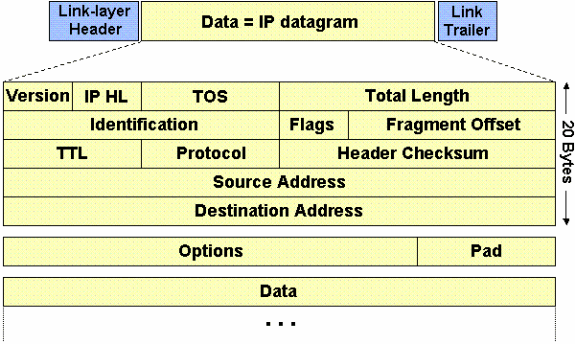
The MTU is the Maximum IP packet size for a given link. Packets bigger than the MTU is fragmented at the point where the lower MTU is found and reassembled further down the chain. MTU is always layer 1 and represents capacity of a physical link . But there are situations where protocols/software need to define MTU manually , eg IP MTU or MPLS MTU .
MSS is Maximum TCP segment Size. Unlike MTU, packet exceeding MSS aren't fragmented, they're simply discarded. MSS is normally decided in the TCP three-way handshake, but some setup might yield path where the decided upon MSS is still too big, leading to dropped packets. The MSS isn't negociated packet per packet, but for a complete TCP session, nor does it take into account TCP/IP headers.MSS is always calculated from MTU to avoid any further fragmentation. In case no MTU value is found MSS with minimum size ( 576 ) will be send ( as you know MSS = MTU - layer3 header + layer 2 header ) . and MTU is maximum packet size an interface can support .
The TCP Maximum Segment Size (MSS) defines the maximum amount of data that a host is willing to accept in a single TCP/IP datagram. This TCP/IP datagram might be fragmented at the IP layer. The MSS value is sent as a TCP header option only in TCP SYN segments. Each side of a TCP connection reports its MSS value to the other side. Contrary to popular belief, the MSS value is not negotiated between hosts. The sending host is required to limit the size of data in a single TCP segment to a value less than or equal to the MSS reported by the receiving host.
Originally, MSS meant how big a buffer (greater than or equal to 65496K) was allocated on a receiving station to be able to store the TCP data contained within a single IP datagram. MSS was the maximum segment (chunk) of data that the TCP receiver was willing to accept. This TCP segment could be as large as 64K (the maximum IP datagram size) and it could be fragmented at the IP layer in order to be transmitted across the network to the receiving host. The receiving host would reassemble the IP datagram before it handed the complete TCP segment to the TCP layer.
For example, when using PPPoE, all the overhead means you needs to reduce the MSS on the way, normally by specifying it on the router where the chokepoint is found, which will then replace the MSS of passing threeway handshake by the correct lower value if it's higher. PPPoE is simply adding 8 bytes (6 bytes PPPoE + 2 bytes PPP) on top of everything (IP+TCP) and is meant to be run over Ethernet at 1500 bytes MTU, hence the 1492 MSS normally configured to make it go through.
Your IP stack will chop off data to be sent up to the MSS, put it in a TCP segment, then put it in one or more IP packets (depending if it's bigger than local MTU settings) before sending it. Intermediate router could chop it down further if they have lower MTU, but they're only affecting the IP Packet itself, not playing into the TCP segment/header.
Configuration for MTU and MSS:
Tunnel xxxx
ip mtu 1372
ip tpc adjust-mss 1332
Cisco recommends a GRE MTU of 1400, that's cool. A GRE tunnel encapsulation requires 24/28 Bytes - as you have stated ( I always go with 28, includes some fudge). So the MTU that the GRE can send is 1400 - 28 = MTU 1372 - not including GRE encapsulation. Don't forget that the Maximum Segment Size is the largest transmissible amount of data that can be sent un-fragmented. So the IP header requires 20 bytes. The TCP header requires 20 bytes = 40 bytes.
Great - so now we have:-
28 Bytes - GRE
20 Bytes - IP
20 Bytes - TCP
Total of 68 Bytes, 1400 - 68 = 1332 this is the MSS, that clients and upstream devices should be setting there to MSS in the TCP handshake.
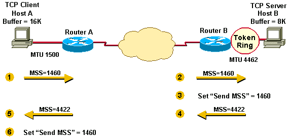
Here is an example from Cisco TechNotes:
Host A compares its MSS buffer (16K) and its MTU (1500 - 40 = 1460) and uses the lower value as the MSS (1460) to send to Host B.
Host B receives Host A's send MSS (1460) and compares it to the value of its outbound interface MTU - 40 (4422).
Host B sets the lower value (1460) as the MSS for sending IP datagrams to Host A.
Host B compares its MSS buffer (8K) and its MTU (4462-40 = 4422) and uses 4422 as the MSS to send to Host A.
Host A receives Host B's send MSS (4422) and compares it to the value of its outbound interface MTU -40 (1460).
Host A sets the lower value (1460) as the MSS for sending IP datagrams to Host B.
1460 is the value chosen by both hosts as the send MSS for each other. Often the send MSS value will be the same on each end of a TCP connection.
In Scenario 2, fragmentation does not occur at the endpoints of a TCP connection because both outgoing interface MTUs are taken into account by the hosts. Packets can still become fragmented in the network between Router A and Router B if they encounter a link with a lower MTU than that of either hosts' outbound interface.
Reference: